


 Purchase Protection
Powerful Protection from Payment to Delivery
Secure and Reliable Payment
Money Back Guarantee
Shipping and Delivery
After-Sales Service
Enter the order reference number received by email to check the status or make payment.
Key Considerations for Designing Active Sonar Transmit and Receive Circuits
The development of modern sonar technology began in the 20th century and was initially applied in the military for the detection, classification, localization, and tracking of underwater targets, as well as for underwater communication and navigation to ensure the underwater safety of ships. With the rapid development of electronic and computer technology, sonar technology has been greatly advanced and gradually applied in civilian fields. Although there are complete sonar detection systems available, most of the signal transmission and reception circuits are specialized, making them expensive and inconvenient for theoretical research. Therefore, this article will study the application of the LM386 operational amplifier in low-power active sonar transmission and reception circuits.
1. LM386 Operational Amplifier
The LM386 is a single-supply audio power amplifier produced by the National Semiconductor Corporation in the United States. It has the advantages of low power consumption, adjustable voltage gain, wide power supply voltage range, few external components, and low total harmonic distortion. It is available in an 8-pin dual in-line package and surface mount package. The internal structure diagram is shown in Figure 1, and the pinout diagram is shown in Figure 2.

Figure 1: Internal Structure Diagram

Figure 2: Pinout Diagram
2. Sonar Transducer
The heart of a sonar transducer is a piezoelectric ceramic transducer. The working principle of a piezoelectric ceramic transducer is as follows: when pressure or tension is applied to the piezoelectric ceramic element, opposite polarities of charges are generated at its two ends, forming a current through the circuit. This effect is known as the piezoelectric effect. When a sonar transducer made of this piezoelectric ceramic is placed in water, it will generate induced charges at its two ends under the action of sound waves. Moreover, the piezoelectric effect is reversible. Applying an alternating voltage to the piezoelectric ceramic element in an active sonar will cause it to vibrate and emit ultrasonic waves.

Figure 3: Sonar Transducer
Sonar can be divided into active sonar and passive sonar based on their operation modes. Active sonar utilizes the transmission circuit to generate periodic or pulsed signals. Under the action of these signals, the sonar transducer emits ultrasonic waves. When the ultrasonic waves propagate in water and encounter obstacles, they will be reflected. The reflected wave signals are received by the sonar reception circuit, and after signal processing, the position and distance of the obstacles can be measured. Passive sonar utilizes the sonar reception circuit to receive the ultrasonic waves emitted by objects in the water to determine their directions.
Design of Active Sonar Transmission and Reception Circuits
Three factors need to be considered when designing an active sonar sensor: center frequency, maximum transmission power, and detection range.
1. Center Frequency Selection:
The choice of center frequency for an active sonar system depends on technical specifications (such as detection range), system structure, and channel characteristics. Typically, the operating frequency for active sonar systems is between 20kHz and 60kHz. Higher frequencies can be used for short-range measurements, while lower frequencies are preferred for long-range measurements due to increased propagation loss. In this study, the center frequency of the active sonar sensor is set at 40kHz.
2. Maximum Transmission Power:
The maximum transmission power refers to the output power of the active sonar transmission circuit, which is the electrical power at the input of the active sonar sensor. A higher maximum transmission power results in a longer detection range. For this study on low-power active sonar ranging, the detection range is set between 20m and 200m. The output power amplified by the LM386 can meet the detection requirements of this study.
3.1 Active Sonar Transmission Circuit:
Various waveforms can be used for sonar transmission signals, such as sinusoidal, single-frequency rectangular pulse, and linear frequency modulation pulse signals. The choice of waveform directly affects the target detection capability of the system and should be determined based on the mission objectives of the sonar system. For this study on low-power active sonar ranging, a sinusoidal signal is chosen as the transmission signal. The active sonar transmission circuit consists of an RC sinusoidal oscillator circuit and a power amplification circuit, as shown in Figure 4.
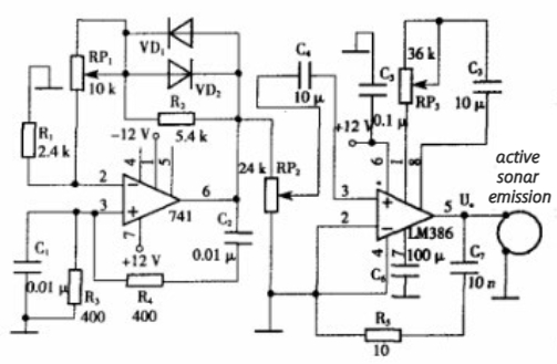
Figure 4 Active sonar transmitter circuit
3.1.1 Generation of Sinusoidal Signal:
The RC bridge oscillator circuit, also known as the RC series-parallel oscillator circuit, is commonly used to generate sinusoidal wave signals with frequencies ranging from 1Hz to 1MHz. In this study, the center frequency of the sonar sensor is 40kHz, and the RC bridge oscillator circuit meets the requirements. Therefore, the RC bridge oscillator circuit is composed of an integrated operational amplifier μA741 and an RC selective network. As shown in Figure 4, the RC selective network, consisting of C1, R3, C2, and R4, is connected between the inverting input and output of μA741, forming a positive feedback loop. The non-inverting input of μA741 is connected to a stable amplitude negative feedback circuit composed of RP1, R2, VD1, and VD2. The diodes VD1 and VD2 provide amplitude stabilization. When the output voltage waveform of the oscillator circuit (pin 6 of μA741) is in the negative half-cycle, VD2 conducts, and its forward conductance rD is in parallel with R2. The larger the negative voltage, the smaller the parallel resistance, resulting in strengthened negative feedback, reduced closed-loop gain, and amplitude stabilization. The same principle applies when the output voltage waveform is in the positive half-cycle, with VD1 conducting.
3.1.2 Power Amplification Circuit:
The internal circuit structure of the LM386, as shown in Figure 1, reveals that resistor R7 is connected from the output to the emitter of V2, forming a feedback path. It, along with R5 and R6, constitutes a feedback network that introduces DC voltage series negative feedback, providing stable voltage gain to the entire circuit. When pins 1 and 8 are open-circuited, the emitter of V1 is approximately at ground potential in the AC path. The dynamic voltage on R5 and R6 serves as the feedback voltage, which is approximately equal to the in-phase input voltage. In other words, it is half of the differential-mode input voltage. Therefore, the feedback coefficient is given by the equation mentioned above, and the voltage gain is calculated accordingly. Since R7 > (R5 + R6), the voltage gain can be approximated as 20. When an external resistor R is connected between pins 1 and 8, the voltage gain can be adjusted within the range of 20 to 200, as shown in the equations provided. In the active sonar transmission circuit shown in Figure 4, an external resistor R of 20kΩ is connected between pins 1 and 8 of the LM386. According to equation (6), the voltage gain of the power amplifier is approximately 21.21. When the load RL is 20Ω, the maximum undistorted output voltage amplitude of the transmission circuit is approximately 11.7V. Therefore, the maximum output power of the transmission circuit can be calculated using the provided equation (8), and the efficiency can be calculated using equation (9). This maximum output power satisfies the power requirements for low-power active sonar detection in this study. The phase compensation circuit composed of R5 and C7 is designed to prevent overvoltage on the load from damaging the power amplification transistor inside the chip. The circuit is powered by a single power supply,
Power Amplification Circuit in the Receiver Circuit
Low-power Active Sonar Receiver Circuit
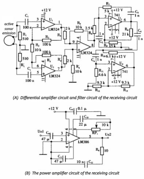
Figure 5 Low-power active sonar receiving circuit
Figure 5 shows the low-power active sonar receiver circuit. The receiver circuit consists of a differential amplifier circuit, a filtering circuit, and a power amplification circuit.
The active sonar sensor receives the ultrasonic waves emitted by the active sonar transmission and converts them into electrical signals through the piezoelectric effect. At this point, the output voltage of the receiving sonar sensor is in the millivolt range. After differential amplification and filtering, the energy of the output signal is still relatively weak, especially in long-distance measurements. Therefore, power amplification is necessary.
The low-power operational amplifier LM386 has an input range in the millivolt level and a voltage gain of 20 to 200. It is applied in the low-power active sonar receiver circuit due to its simplicity and low noise, which reduces the area of susceptibility to external electromagnetic interference or avoids interference. The LM386 has a bandwidth of up to 300kHz, allowing it to amplify the output signal of the receiver circuit.
As shown in Figure 5(b), an external resistor RP1 = 1.8kΩ is connected between pins 1 and 8 of the LM386, and the voltage gain can be calculated using equation (6) as Au≈32.68. The function of R6 and C12 is to provide phase compensation, similar to the transmission circuit, to prevent overvoltage across the power amplifier tube inside the chip. The circuit is also powered by a single power supply, and the output terminal (pin 5) should be connected to the load after an output capacitor.
When applying the LM386 in the low-power active sonar transmission and receiver circuits, the strength of the input signal needs to be considered. The amplitude of the input signal should be adjusted appropriately to obtain the maximum undistorted signal at the output terminal, providing an ideal signal source for sonar signal processing.
3. Conclusion
This article introduces the design of the low-power active sonar transmission and receiver circuits, and provides a detailed explanation of the application of the LM386 operational amplifier in these circuits. It also discusses the generation of sinusoidal signal sources, the differential amplification circuit in the receiver circuit, and the analog filtering circuit. In the initial stage of the research on autonomous navigation of underwater submarine models, this experiment observed the waveforms of the sonar sensor input and the receiver circuit after amplification by the LM386 using an oscilloscope, as shown in Figure 6.
Waveforms of the sonar sensor input and the receiver circuit after amplification by the LM386
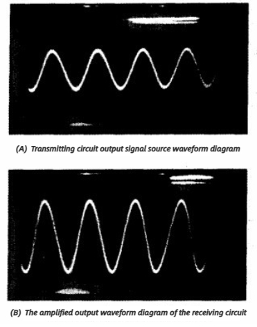
Figure 6 Waveforms of the sonar sensor input and the receiver circuit after amplification by the LM386
The audio operational amplifier LM386 has certain versatility and scalability when applied in the low-power active sonar transmission and receiver circuits. It can also be used when the form of the low-power active sonar transmission signal source changes. This design provides a simple signal source for studying the signal processing of low-power active sonar detection.


Company
About UsContact UsTerms & ConditionsPrivacy StatementPayment,Shipping & InvoiceRefund & Return PolicyWarranty PolicyFrequently asked questionHolidays for Chinese Mid-Autumn Festival and National Day in 2023 Copyright © 2022-2024 Power by Chipdatas Trading Limited. All Rights Reserved.