


 Purchase Protection
Powerful Protection from Payment to Delivery
Secure and Reliable Payment
Money Back Guarantee
Shipping and Delivery
After-Sales Service
LM386 Audio Power Amplifier Circuit's Prevention and Control of Self-excitation and Precautions
LM386 is widely used in audio amplification circuits. In most cases or when used alone, LM386 works properly. However, when used in conjunction with other circuits, it may experience phenomena such as self-oscillation and reduced sensitivity. This article mainly introduces countermeasures and precautions to address these issues.
1. Countermeasures for self-oscillation and whistling
1.1 Excessive input signal
To address whistling caused by excessive input signals, a resistor-capacitor network can be added between pins 1 and 8 of LM386. The resistance value of R can be determined through experimentation or replaced with a trim potentiometer W. If the signal is still too strong, leave pins 1 and 8 of LM386 floating.
1.2 High-frequency self-oscillation
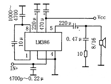
Figure 1: Principle of high-frequency self-oscillation prevention circuit
The principle of preventing high-frequency self-oscillation is shown in Figure 1. To address whistling caused by high-frequency self-oscillation, connect a 4700pF~0.22μF ceramic capacitor between the signal input terminal and ground, and connect a 1000~4700pF ceramic capacitor between pin 8 and ground. When operating in single-ended input mode, make sure the unused input terminal is grounded rather than left floating.
1.3 Low-frequency self-oscillation
To address whistling caused by low-frequency self-oscillation, try connecting a 6.8~22kΩ resistor between the input terminal and ground. Increase the value of the filtering capacitor at pin 8 to 1000μF. When designing the PCB, position LM386 as close as possible to the power output terminal.
1.4 Other methods
When using other brand products such as GL386 or KA386, some ICs may be sensitive to high-frequency audio. You can connect a 0.1μF ceramic capacitor between pin 7 and ground, and a bipolar 0.1μF ceramic capacitor between pins 4 and 6 (note: different from grounding pin 8).
2. Precautions
Although the application of LM386 is straightforward, a slight lack of attention, especially during power-on and power-off moments, or when performing certain operations like plugging or unplugging audio jacks, or adjusting volume knobs, can introduce transient shocks that generate annoying noise on the speaker.
1. When designing the PCB, try to place all peripheral components as close as possible to LM386. Use relatively thicker ground traces. Route the input audio signal path parallel to minimize interference, and do the same for the output.
2. Choose a quality potentiometer for volume adjustment. Avoid poor-quality ones, as they can harm your ears. A 10K potentiometer is most suitable, as higher resistances can also affect audio quality.
3. Change the gain by connecting a capacitor (positive terminal) between pins 1 and 8. When disconnected, the gain is 20. If you don't need high gain, you can omit the capacitor. This reduces costs and brings benefits.
4. Whenever possible, use balanced audio inputs/outputs. The benefit is that the "+" and "-" output terminals effectively cancel common-mode signals, suppressing common-mode noise.
5. Proper power handling is also crucial. If the system has multiple power sources, different rise and fall times will occur due to varying voltages, loads, and decoupling capacitor arrangement. One feasible method is to connect the power source with shorter power-on and power-off times to +12V, and select a power source with relatively slower rise time as the Vs for LM386, but never lower than 4V.
6. The bypass capacitor at pin 7 is essential. In practical applications, the BYPASS terminal must be externally connected with an electrolytic capacitor to ground, as it helps filter out noise. After the operation has stabilized, the voltage on this pin is approximately half of the power supply voltage. Increasing the capacitance slows down the rise and fall rate of the DC reference voltage, effectively suppressing noise. The noise during power-on and power-off is caused by transient jumps in this bias voltage, so this capacitor should not be omitted.
7. Reduce the coupling capacitor in the output stage. This capacitor serves two purposes: DC blocking and AC coupling. It isolates the DC voltage, as high DC voltage can potentially damage the speaker coil. It also couples the audio AC signal. Together with the speaker load, it forms a first-order high-pass filter. Reducing the capacitance value helps decrease the amplitude and width of noise energy impacts. However, decreasing it too much will increase the cutoff frequency (fc=1/(2π*RL*Cout)). After testing, it is found that 10uF/4.7uF is the most suitable value.


Company
About UsContact UsTerms & ConditionsPrivacy StatementPayment,Shipping & InvoiceRefund & Return PolicyWarranty PolicyFrequently asked questionHolidays for Chinese Mid-Autumn Festival and National Day in 2023 Copyright © 2022-2024 Power by Chipdatas Trading Limited. All Rights Reserved.