


 Purchase Protection
Powerful Protection from Payment to Delivery
Secure and Reliable Payment
Money Back Guarantee
Shipping and Delivery
After-Sales Service
Design and Realization of LM386 Audio Amplifier Oscillator Circuit
LM386 is a low-power audio amplifier integrated circuit, which is available in an 8-pin dual in-line plastic package. It operates at a voltage range of 4V to 15V and can deliver an output power of 300mW on an 8Ω load when the power supply voltage is 12V. LM386 can be conveniently used to create various oscillators.
1. Simplest Oscillator
Simplest Oscillator Circuit Diagram
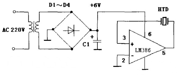
Refer to Figure 1. By connecting a piezoelectric ceramic piece (HTD) between the output terminal and the inverting input terminal of LM386, positive feedback is formed, resulting in oscillation. Here, HTD serves as both the feedback capacitor and the sound-emitting device.
Component Parameters in the Figure: D1 to D4 are 1N4001, C1 = 220pF, HTD refers to the piezoelectric ceramic piece with a sound chamber.
2. Astable Oscillator
Astable Oscillator Circuit Diagram
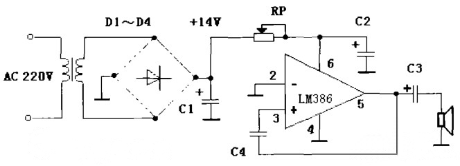
Refer to Figure 2. LM386, together with C3, C4, and the speaker, forms a simple oscillator. RP and C2 cause this oscillator to produce astable oscillation. Upon powering on, since the initial voltage of C2 is zero, LM386 does not operate and the power supply charges C2 through RP. When the charging voltage of C2 exceeds a certain value, the LM386 oscillator starts oscillating. As the amplitude increases, the current consumed by the oscillator also increases. This current flows through RP, resulting in an increased voltage drop across RP and a continuous decrease in the voltage at pin 6 of LM386, which supplies power to the amplifier. Eventually, LM386 stops working, and the oscillator ceases oscillation. The power supply charges C2 again through RP, raising the voltage at the terminal of C2. When the voltage at the terminal of C2 reaches a certain value, LM386 oscillator starts oscillating again. This cycle repeats, generating astable oscillation, and the speaker emits a "beep, beep, beep..." sound.
Component Parameters in the Figure: D1 to D4 are 1N4001, C1 = C3 = 220μF, C2 = 47μF, C4 = 0.01μF, RP = 4.7K.
3. Electronic Piano
Electronic Piano Circuit Diagram
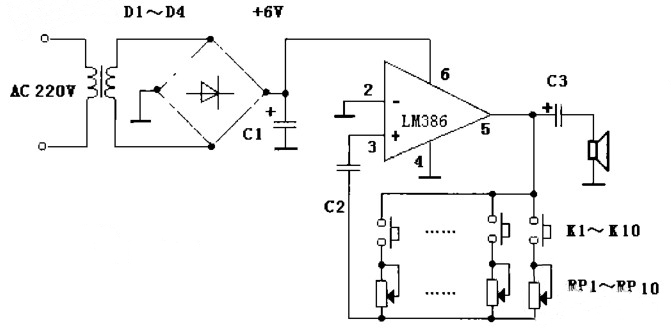
Figure 3 shows a simple electronic piano circuit. At the 3rd pin of LM386, there is an internally built-in 10KΩ resistor connected to ground. This built-in resistor, along with RP1 to RP10, which are ten octave resistors, forms the timing resistors of the oscillator. C2 is the timing capacitor. By adjusting the values of RP1 to RP10, the speaker can sequentially emit musical notes from the low octave "1, 2, 3" to the high octave "1, 2, 3". KI to K10 represents the piano key switches.
Component Parameters in the Figure: Cl = C3 = 220μF, C2 = 2200μF, RP1 to RP10 are adjustable resistors with a range of 85K.
4. Square Wave Oscillator
Square Wave Oscillator Circuit Diagram
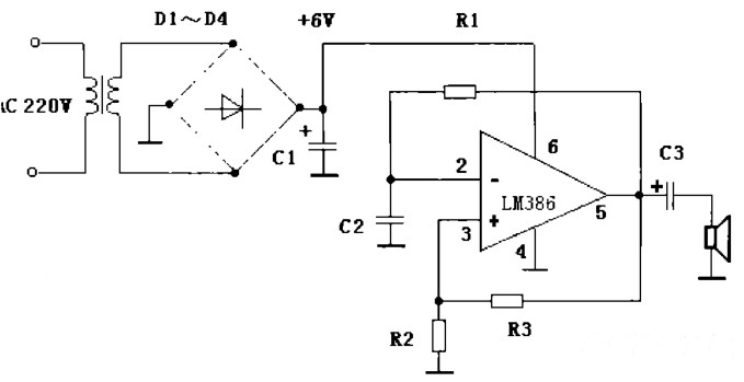
Figure 4 shows a square wave oscillator constructed with LM386. R1 is the timing resistor, and C2 is the timing capacitor. R2 and R3 provide voltage bias to the inverting input terminal of LM386. Upon powering on, since the voltage at the terminal of C2 cannot change suddenly, the inverting input terminal (pin 2) of LM386 is set to a low level and pin 5 represents the midpoint of the OTL output stage of the amplifier, which is static at 1/2Voc. After being divided by R2 and R3, this voltage is supplied to the non-inverting input terminal (pin 3), and it is obviously higher than the voltage at pin 2. Therefore, pin 5 outputs a high level. This high level charges C2 through R1. When the voltage at the terminal of C2 exceeds the voltage at pin 3, pin 5 outputs a low level. C2 then discharges through R1 and pin 5. When C2 is fully discharged, the voltage at pin 2 decreases and becomes lower than the voltage at pin 3. Pin 5 outputs a high level again. This cycle repeats, creating oscillation in the circuit. The oscillation signal drives the speaker to produce sound through C3.
Component Parameters in the Figure: C1 = C3 = 220μF, C2 = 0.33μF, R1 = 22K, R2 = 1K, R3 = 9.4K.
5. Sinewave Oscillator
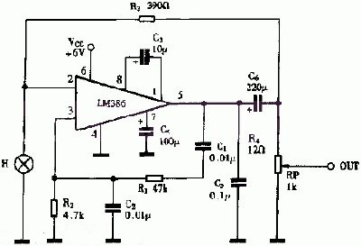
Sinewave Oscillator Circuit Diagram
Figure 5 depicts a sinewave oscillator created using LM386. The circuit adopts the Wien bridge oscillator configuration, resulting in extremely low distortion in the output signal. The small light bulb (H) and resistor R3 form a negative feedback circuit, which keeps the amplitude of the oscillator output signal stable and maintains low distortion. When the values of capacitors C1 and C2 are the same, the oscillation frequency can be calculated using the formula f = 1 / (2C1 R1R2). With the given data in the diagram, the sinewave frequency is 1kHz. In practical implementation, a small light bulb with a voltage of 3V and current of 15mA can be used for H.


Company
About UsContact UsTerms & ConditionsPrivacy StatementPayment,Shipping & InvoiceRefund & Return PolicyWarranty PolicyFrequently asked questionHolidays for Chinese Mid-Autumn Festival and National Day in 2023 Copyright © 2022-2024 Power by Chipdatas Trading Limited. All Rights Reserved.