


 Purchase Protection
Powerful Protection from Payment to Delivery
Secure and Reliable Payment
Money Back Guarantee
Shipping and Delivery
After-Sales Service
Transformers Explained: FAQs and Key Concepts
This article will be divided into three parts: individual transformers, parallel transformers, and redundancy requirements for bulk power transformers.
1 Individual Transformer
In this section, we will focus on the protection methods for individual transformers. The diagram below illustrates the configuration of a bank with primary fuses used for protection. For larger or critical banks, overall differential protection can be implemented by employing current transformers (CTs) on the primary bushings of the transformer. The diagram shows a common connection with delta on the source (primary) side and wye-grounded on the secondary side. Other possible connections include delta-delta, wye-wye, or primary-wye-secondary-delta configurations.
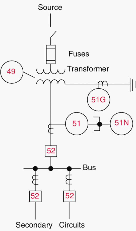
Figure 1 Transformer protection without primary-side circuit breaker
It is important to note that secondary circuits should be equipped with 51 and 51N relays. Therefore, the transformer secondary breaker and relays can be omitted unless there is another source connected to the secondary bus. The 51N relay can be omitted if a 51G relay is available.
For transformer banks with primary breakers, the protection scheme is summarized in Figure 2.
Relay 51G provides backup protection for secondary bus and feeder faults and must be time-coordinated with other ground relays protecting the various feeder circuits on the secondary bus. Similarly, phase relays 51 must be coordinated with the phase relays on the feeders. The common connection is shown with delta on the source (primary) side and wye-grounded on the secondary side. Other possible connections include delta-delta, wye-wye, primary-wye-secondary-delta, three-winding, or autotransformer configurations.
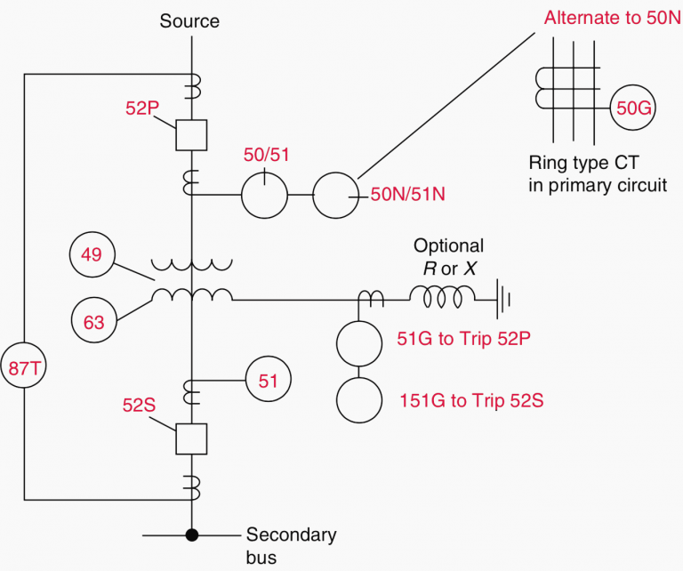
Figure 2 – Transformer protection with primary-side circuit breaker
Please note that "52S may be omitted in some applications requiring 151G to coordinate with and trip the secondary circuit devices if used."
2 Parallel Transformer
In this section, we will discuss the protection methods for transformer banks where the secondaries are connected together by a bus tie breaker. The protection schemes are summarized in the following diagrams (a, b, c).
This arrangement is commonly seen in substations with large or critical loads, particularly in industrial plants. The loads are supplied from separate buses that are connected by a bus tie breaker (52T), which can be operated in either a normally closed (NC) or normally open (NO) position.
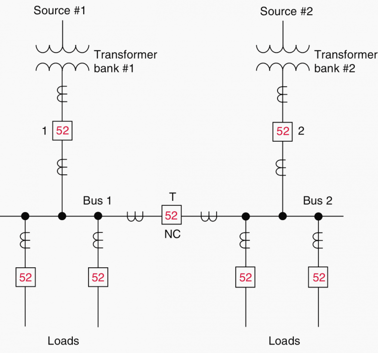
Figure 3a Single line diagram of transformer and secondary bus protection for a typical double-source supply with secondary tie and breaker
If the bus tie breaker is operated in the NO position, the protection methods shown in the first and second pictures are applicable. If the bus tie breaker is operated with 52T in the NC position, the protection methods shown in the first and second pictures are applicable with modifications on the secondary side.
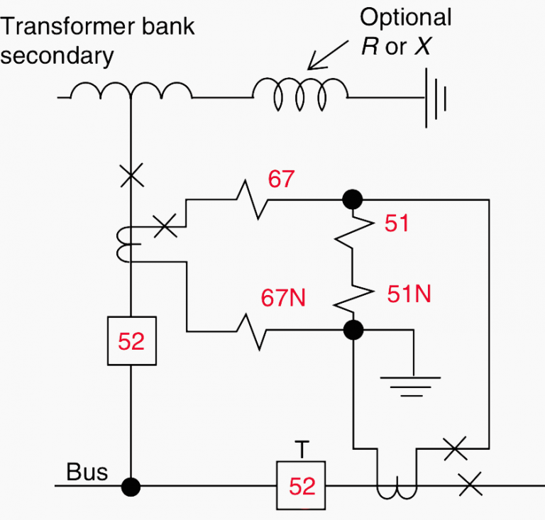
Figure 3b Secondary protection with high-side fuses
When the bus tie breaker is closed, there is a potential for power flow interchange between the two sources. In this case, current flows from one source through its transformer, the secondary buses, and back through the other transformer to the second source. However, this operation is generally undesired and prohibited.
"To prevent this operation, directional time-overcurrent relays (67, 67N) are applied to each transformer."
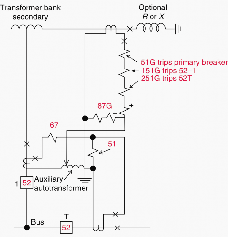
Figure 3c Secondary protection with high-side breaker
The single-line connections are shown in Figures 3b and 3c, while a complete three-line connection is illustrated in the following figure.
Note: The directional time-overcurrent relays (67, 67N) only operate for fault current flowing into the transformer and will trip the secondary breaker (52-1 or 52-2). This is crucial in removing a secondary fault source for faults in the transformer bank. The phase relays (67) can be set at a low value, close to the minimum tap setting.
Load current typically flows through the relay, but usually not in the operating direction. It is important to ensure that the maximum load current does not exceed the continuous rating of the low tap. The time setting for the 67 relay must be coordinated with the protection on the transformer primary. In the case of the ground relay, it can be set to the minimum setting and time since coordination is not necessary.
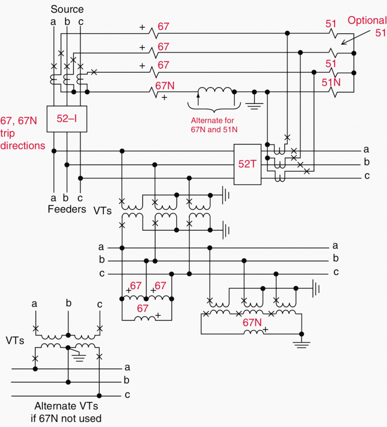
Figure 4 Three-line connections for reverse-phase and partial differential backup protection
The inverse-time overcurrent relays (51, 51N) offer bus protection and act as backup protection for the feeder circuits. These relays trigger both 52-1 (or 52-2) and 52T. This type of connection is known as partial differential, and these units should be time-coordinated with the protection on the various feeders connected to the bus.
"Only two-phase relays are necessary, but the third relay (optional in Figure 4) provides additional redundancy. In cases where a ground differential is used, as shown in Figure 3c, 67N and 51N relays are omitted."
Ground-fault backup protection is provided by the inverse-time overcurrent relays 51G, 151G, and 251G (Figure 3a, 3b, 3c). Relay 251G offers bus ground-fault protection and serves as backup for the feeder circuit ground relays. It must be time-coordinated with these relays. Relay 251G trips the bus tie 52T, as the fault could be present on either the bus or the associated feeders.
If the fault still exists when the bus tie is open, relay 151G trips breaker 52-1 (or 52-2). Therefore, coordination between relay 151G and 251G is crucial. If the fault persists, it could be located between the secondary breaker, within the transformer winding, or in the grounding impedance.
Relay 51G, set to coordinate with 151G, functions as the last resort. It trips the high-side or primary breaker to remove the transformer from service.
3 Redundancy Requirements for Bulk Power Transformers
When transformers are connected to bulk power systems, it is essential to address the redundancy requirements for related protection. To achieve the necessary redundancy, two separate differential schemes can be implemented.
"Redundancy for transformer faults can also be achieved through a combination of a differential scheme and sudden pressure protection."
In such applications, the sudden pressure protection must be supplemented with additional protection for faults occurring in the transformer bushings and leads. Sudden pressure devices alone will not respond to faults in these areas. Various combinations of methods can be employed to achieve redundant schemes for disconnecting the transformer from the system when a high-side breaker is not functioning. For example, two separate transfer trip systems can be utilized, although they tend to be expensive. A more cost-effective alternative is to combine a transfer trip scheme with a faulty switch. It may be possible to introduce a delay in closing the fault switch for a few cycles to allow time for the operational transfer trip scheme to de-energize the failed transformer before the fault switch closes. This approach ensures that the power system is spared from being subjected to a solid fault when the fault switch closes, as long as the transfer trip scheme is functioning properly.
When a high-side breaker is applied but fails to operate, breaker failure protection becomes necessary to isolate a faulty transformer. The breaker failure scheme may require the application of a fault switch, a transfer trip scheme, or a second interrupting device if there are no other local breakers available to isolate the transformer.
4 FAQ
1. What is the purpose of a transformer?
Transformers are used for a wide range of applications. They are used to decrease the voltage in power circuits to operate low-voltage devices like doorbells and toy electric trains. Conversely, transformers can also increase the voltage from electric generators to enable the transmission of electric power over long distances.
2. What are the three types of transformers?
There are three primary types of voltage transformers (VT): electromagnetic, capacitor, and optical.
3. What is the basic principle of a transformer?
A transformer consists of two electrically isolated coils and operates based on Faraday's principle of "mutual induction." According to this principle, an electromotive force (EMF) is induced in the secondary coil of the transformer by the magnetic flux generated by the voltages and currents flowing in the primary coil winding.
4. Can a transformer convert AC to DC?
A transformer is designed to transfer energy from one circuit to another through magnetic coupling. While an alternating current (AC) can create a magnetic flux in the transformer's core, inducing voltage in the secondary winding, a transformer is not capable of converting AC to direct current (DC).
5. What are the main components of a transformer?
A transformer consists of three basic parts:
a. An iron core that serves as a magnetic conductor.
b. A primary winding or coil of wire.
c. A secondary winding or coil of wire.
6. How are transformers classified?
Transformers can be classified into two categories based on the construction:
a. Core type
b. Shell type
They can also be classified based on their service in the power system:
a. Power transformers
b. Distribution transformers
7. Can a transformer work with DC?
Transformers do not allow direct current (DC) input to flow through them. This is known as DC isolation. Since a changing magnetic field is required to induce voltage across the secondary component, and DC does not produce such a field, transformers are not suitable for DC operation.
8. How is a transformer created?
A transformer is created by winding two separate conductors around a common iron core. Applying an alternating voltage to the primary conductor generates a current that establishes a magnetic field around itself. This phenomenon is known as mutual inductance.
9. What are the components of the no-load current in a transformer?
The no-load current of a transformer consists of two components:
a. Magnetization Current (iM): This current is necessary to produce the flux in the transformer core.
b. Core-loss Current (ih+e): This current compensates for hysteresis and eddy current losses.
10. Which type of transformer core is the most efficient?
The shell core is considered the most efficient transformer core. It is composed of E- and I-shaped sections of metal that are butted together to form the laminations, as shown in Figure (4).
11. What is the power factor of a transformer?
The power factor of a distribution transformer typically ranges between 0.75 to 0.80 when the secondary is connected to unity power factor (u.p.f) loads.
12. Why do we need transformers?
Transformers are essential in improving the safety and efficiency of power systems by adjusting voltage levels as required. They find extensive use in residential and industrial applications, particularly in the distribution and regulation of power over long distances.
13. What is the difference between a step-up transformer and a step-down transformer?
A step-up transformer is designed to increase the voltage from the primary winding to the secondary winding, typically achieved by having more turns in the secondary winding compared to the primary winding. On the other hand, a step-down transformer is designed to decrease the voltage from primary to secondary.
14. Are transformers dangerous?
There is no conclusive evidence to suggest that exposure to magnetic fields from powerlines, substations, transformers, or other electrical sources, regardless of proximity, causes any adverse health effects.
15. Why is the transformer rating expressed in kVA instead of kW?
The copper losses (I²R losses) in a transformer depend on the current passing through the transformer winding, while the iron losses, core losses, or insulation losses are primarily dependent on voltage. Therefore, the transformer rating is commonly expressed in terms of volt-amps (VA) or kilovolt-amps (kVA) rather than in watts (W) or kilowatts (kW).


Company
About UsContact UsTerms & ConditionsPrivacy StatementPayment,Shipping & InvoiceRefund & Return PolicyWarranty PolicyFrequently asked questionHolidays for Chinese Mid-Autumn Festival and National Day in 2023 Copyright © 2022-2024 Power by Chipdatas Trading Limited. All Rights Reserved.