


 Purchase Protection
Powerful Protection from Payment to Delivery
Secure and Reliable Payment
Money Back Guarantee
Shipping and Delivery
After-Sales Service
Enter the order reference number received by email to check the status or make payment.
What is a crystal oscillator? Introduction to the role and working principle of crystal oscillator
Here, I will introduce the relevant knowledge of crystal oscillator to you, including the definition, manufacturing process, internal structure, working application, and parameters related to the frequency of crystal oscillator.
1. What is a crystal oscillator?
Crystal oscillator is one of the most commonly used electronic components in electronic circuits, which is composed of a quartz crystal oscillator and also known as a crystal oscillator. The crystal oscillator is an electronic oscillator circuit that utilizes the inverse piezoelectric effect, which generates mechanical deformation on a piezoelectric material by applying an electric field, and uses the mechanical resonance of the vibrating crystal to generate an electric signal with a very precise frequency.
Crystal oscillators have advantages such as high stability, high quality factor, small size, and low cost, which make them superior to other resonators such as LC circuits, ceramic resonators, and tuning fork in electronic circuits.
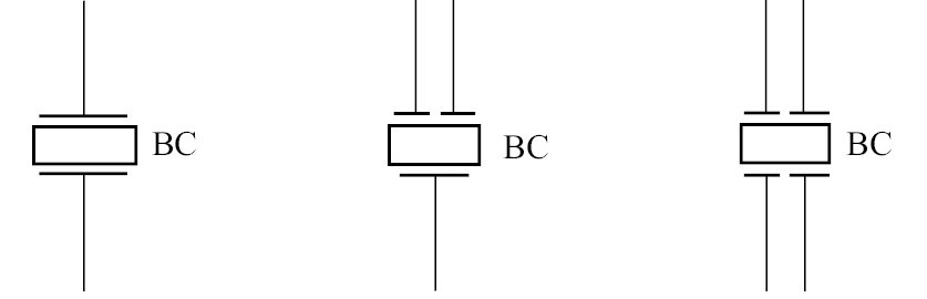
In the circuit, crystal oscillators are generally represented by the letters "X", "G", or "Z", and their unit is Hz. The graphical symbol of a crystal oscillator is shown in the figure below:
2. How are crystal oscillators made? --How to change from a quartz blank to a crystal oscillator?
Quartz blanks are used as resonant elements in oscillating circuits. When influenced by voltage potential, it vibrates and oscillates at its fundamental frequency. This vibration is interrelated with the circuit, supporting mechanical resonance and vice versa. Crystals are used in the feedback loop of oscillators to limit the frequency of the oscillator.
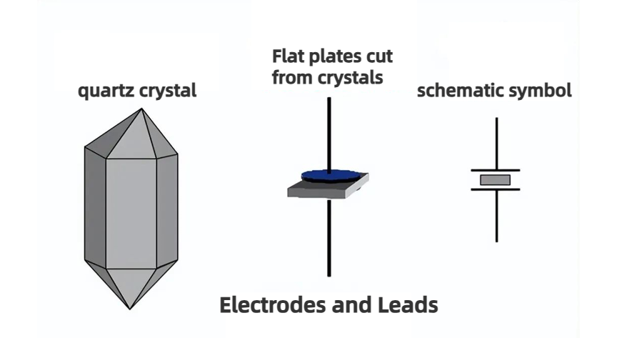
The figure below shows the diagram from the original quartz crystal material to the final crystal oscillator.
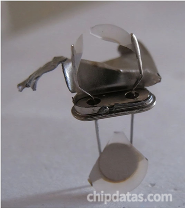
3. What is the inside of the crystal oscillator like?
As shown in the figure below, the entire crystal is wrapped in a metal shell.
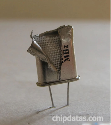
When the metal case is removed, we can see a blanket-like mesh structure that protects the crystal from mechanical damage.
In the image below, we can see the crystal oscillator is placed inside the mesh housing which is encased in the outer metal housing.
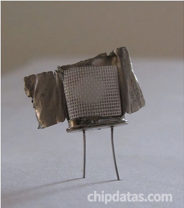
When the metal covering is removed we can see the quartz crystal plate and how it connects to the external electrodes as shown in the image below.
4. How a Crystal Oscillator Works
The quartz crystal oscillator is a resonator device made using the piezoelectric effect of quartz crystal. Its basic structure is a thin slice cut from a quartz crystal at a certain angle, with silver layers coated on its two corresponding surfaces as electrodes. A lead wire is welded to each electrode and connected to a pin, and then a packaging shell is added to form the quartz crystal resonator, also known as crystal or crystal oscillator. Its products are generally packaged in metal shells, but can also be packaged in glass, ceramics, or plastic.
The piezoelectric effect of quartz crystal refers to the mechanical deformation of the crystal chip when an electric field is applied to the two electrodes of the quartz crystal. Conversely, if mechanical pressure is applied to the two sides of the chip, an electric field will be generated in the corresponding direction of the chip. This physical phenomenon is called the piezoelectric effect. If an alternating voltage is applied to the two poles of the crystal chip, the chip will vibrate mechanically, and the mechanical vibration of the chip will also generate an alternating electric field.
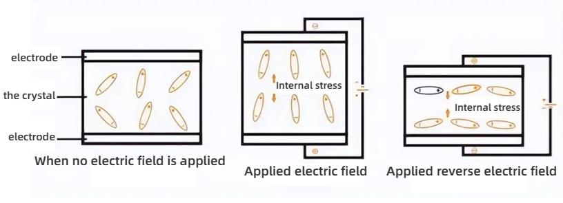
In general, the amplitude of the mechanical vibration of the chip and the amplitude of the alternating electric field are very small. However, when the frequency of the applied alternating voltage is a certain specific value, the amplitude significantly increases, much larger than that at other frequencies. This phenomenon is called piezoelectric resonance, which is very similar to the resonance phenomenon of the LC circuit. The resonant frequency of the quartz crystal is related to the cutting method, geometry, size, and other factors of the crystal chip.
When the crystal is not vibrating, it can be regarded as a flat capacitor, called the static capacitance C, which is related to the geometric size and electrode area of the crystal chip and is generally about several picofarads to several tens of picofarads. When the crystal vibrates, the inertia of the mechanical vibration can be equivalent to an inductance L.
5. Equivalent Circuit of Crystal Oscillator
In a crystal oscillator, a crystal is properly cut and mounted between two metal plates, as shown in the left image below. Its electrical equivalent is shown in the right image below.
In reality, the behavior of the crystal is like a series RLC circuit, composed of:
- A low resistance resistor Rs
- A large inductance Ls
- A small capacitance Cs
- A capacitor Cp connected in parallel to its electrodes
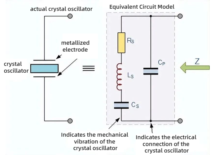
The equivalent circuit of the quartz crystal shows a series RLC circuit, which represents the mechanical vibration of the crystal, and a capacitor Cp connected in parallel, which represents the electrical connection to the crystal. Quartz crystal oscillators tend to operate towards their "series resonance".
1. Impedance frequency of crystal oscillator
The equivalent impedance of the crystal has a series resonance, where Cs resonates with the inductance Ls at the operating frequency of the crystal. This frequency is called the crystal series frequency, ƒs. In addition to this series frequency, a parallel resonance is established when Ls and Cs resonate with the parallel capacitor Cp, as shown in the figure below, creating a second frequency point.
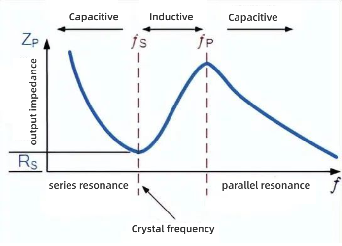
The slope of the crystal impedance above indicates that as the frequency increases at its terminals, at a particular frequency, the interaction between the series capacitor Cs and the inductor Ls produces a series resonant circuit that lowers the crystal impedance to a minimum and equals Rs. This frequency point is called the crystal series resonance frequency ƒs, below which the crystal is capacitive.
As the frequency increases above this series resonance point, the behavior of the crystal is like an inductor until the frequency reaches its parallel resonance frequency ƒp.
At this frequency, the interaction between the series inductor Ls and the parallel capacitor Cp produces a parallel tuned LC resonant circuit, so the impedance at both ends of the crystal reaches its maximum value.
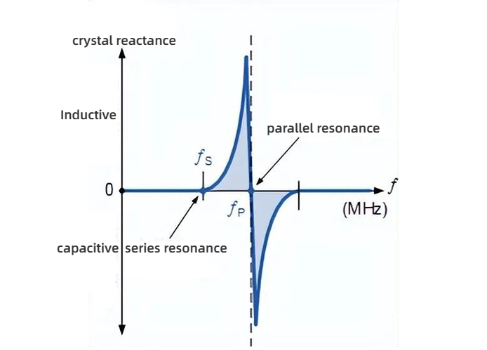
Therefore, according to the circuit characteristics, quartz crystals can be used as capacitors, inductors, series resonant circuits, or parallel resonant circuits. To illustrate this more clearly, we can look at the relationship between crystal reactance and frequency in the figure below.
2. Reactance frequency of crystal oscillator
As shown in the figure below, the slope of the reactance with respect to the above frequency indicates that the series reactance at frequency ƒs is inversely proportional to Cs, as the crystal is capacitive below ƒs and above ƒp.
Between the frequencies ƒs and ƒp, the crystal exhibits inductance due to the two parallel capacitors canceling each other out.
3. Series resonance frequency
The series resonance frequency can be obtained according to the equivalent circuit diagram shown in the figure below:

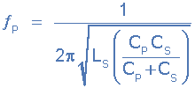
4. Parallel resonance frequency
When the reactance of the series LC branch is equal to the reactance of the parallel capacitor Cp, a parallel resonance frequency ƒp occurs, which is given by:
6. Quartz Crystal Oscillator Example
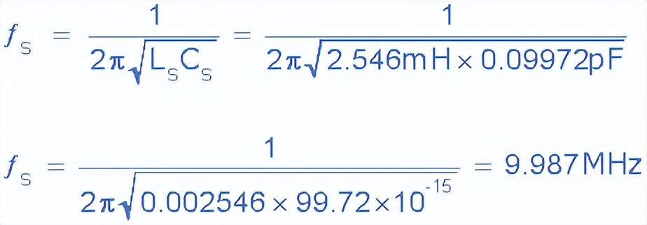
Quartz crystals have the following parameters: series resistance Rs = 6.4Ω, series capacitance Cs = 0.09972pF, series inductance Ls = 2.546mH. If the measured parallel capacitance across the crystal is Cp = 28.68pF, the fundamental and overtone resonant frequencies of the crystal can be calculated.
The series resonant frequency fs of the crystal can be calculated using the following formula:
The parallel resonant frequency fp of the crystal can be calculated using the following formula:
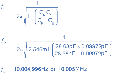
It can be seen that the difference between the fundamental resonant frequency fs and the overtone resonant frequency fp of the crystal is very small, about 18kHz (10.005MHz - 9.987MHz). However, within this frequency range, the quality factor Q of the crystal is very high because the inductance of the crystal is much higher than its capacitance or resistance.
The quality factor Q of the crystal oscillator can be calculated using the following formula:
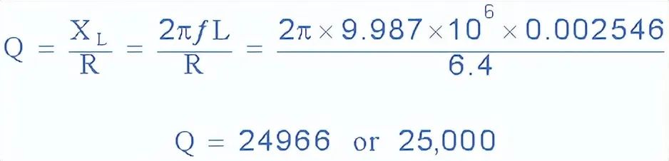
For this example of a quartz crystal, Q is approximately 25,000, which is due to its high X L / R ratio.
The quality factor of most crystals is between 20,000 and 200,000, while the quality factor of a good LC tuning circuit is usually much less than 1,000.
This high quality factor value helps the crystal to have higher frequency stability at its operating frequency, making it an ideal choice for building high-frequency oscillator circuits.
The resonant frequency of a quartz crystal is similar to the resonant frequency of an electrically tuned LC resonant circuit, but with a much higher Q factor, mainly due to its low series resistance Rs. Therefore, quartz crystals are an excellent component choice for building high-frequency oscillator circuits.
The oscillation frequency range of a typical crystal oscillator can be from about 40kHz to far above 100MHz, depending on their circuit configuration and the amplification equipment used. The cutting of the crystal also determines its behavior, as some crystals will vibrate at more than one frequency, producing additional oscillations known as overtones.
In addition, if the thickness of the crystal is not parallel or uniform, it may have two or more resonant frequencies, both of which have fundamental and harmonic frequencies, such as second or third harmonic.
7. Main Factors Affecting Crystal Oscillation Frequency
1. Changes in operating point
We have previously learned about transistors and the importance of the operating point. For crystal oscillators, the stability of this operating point needs to be given more consideration.
The active devices used are adjusted to their linear region of operation, and this point moves due to temperature changes, which affects stability.
2. Temperature changes
The oscillator circuit in a crystal oscillator includes various components such as resistors, capacitors, and inductors. All of their parameters depend on temperature, and their values are affected by temperature changes, which in turn affects the frequency of the oscillator circuit.
3. Power supply effects
Changes in the power supply can affect the frequency of the oscillator. Power supply variations cause changes in Vcc, which affects the frequency of the resulting oscillation.
To avoid this situation, a regulated power supply system, known as RPS, is implemented.
4. Output load changes
Changes in output resistance or output load can affect the frequency of the oscillator. When a load is connected, the effective resistance of the energy storage circuit changes.
The Q factor of the LC tuning circuit changes, which affects the output frequency of the oscillator.
5. Changes in inter-element capacitance
Inter-element capacitance is the capacitance that arises from the PN junction materials in components such as diodes and transistors due to the charge present during their operation.
Inter-element capacitance changes due to various reasons such as temperature and voltage. However, this problem can be solved by connecting a capacitor across the problematic inter-element capacitance.
6. Q factor
The Q factor in the oscillator must be high. The Q factor in a tuned oscillator determines selectivity. Since the Q factor is directly proportional to the frequency stability of the tuning circuit, the Q factor should be kept high.
If the Q factor changes, it will affect frequency stability.
These are some of the key points about the working principle of crystal oscillators. We hope you find this information helpful.


Company
About UsContact UsTerms & ConditionsPrivacy StatementPayment,Shipping & InvoiceRefund & Return PolicyWarranty PolicyFrequently asked questionHolidays for Chinese Mid-Autumn Festival and National Day in 2023 Copyright © 2022-2024 Power by Chipdatas Trading Limited. All Rights Reserved.