- Deliver to
 USLanguageEnglish


Enter the order reference number received by email to check the status or make payment.
 Purchase Protection
Powerful Protection from Payment to Delivery
Secure and Reliable Payment
Money Back Guarantee
Shipping and Delivery
After-Sales Service
Various circuits composed of LM386
The LM386 power amplifier integrated circuit has a wide operating voltage range, with a minimum of 4V and a maximum of 15V. Its static power consumption is only 4mA, and its maximum gain is 46dB, which is equivalent to 200 times. The circuit is simple and requires few peripheral components, making it suitable for electronic enthusiasts to create various circuits. Below are various application circuits made with LM386.
1. Infrared Sound and Light Alarm Circuit
An infrared sound and light alarm circuit composed of 555, LM386, and KD9562.
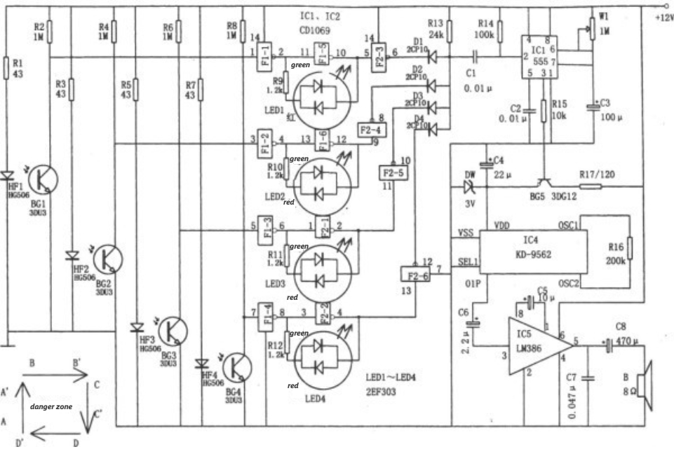
Figure 1: Infrared Sound and Light Alarm Circuit
The circuit shown in Figure 1 is an infrared sound and light alarm circuit. The circuit consists of AND gate circuit, monostable delay circuit, four-channel infrared transmission and reception circuit, trigger and dual-color light-emitting circuit, and audio alarm circuit. This alarm is used to sound an alarm when someone enters the alert area, as shown in the diagram. The infrared light-emitting diodes HF1~HF4 and the infrared receiving paired tubes BG1~BG4 (3DU31) form four pairs of transmission and reception alert lines.
If someone crosses the alert line and blocks the infrared beam, the corresponding paired tube will be cut off, resulting in a high level input for the corresponding NAND gate. This generates a negative differential pulse at the output of the NAND gate composed of D1~D4, which triggers the pin 2 of IC3 (555), causing IC3 to be set. The pin 3 of IC3 outputs a high level, saturating BG5 and powering IC4 (KD-9562), which emits the alarm sound. The monostable circuit in IC3 determines the sound duration, with the delay width td=1.1Rw1R3. The delay alarm time corresponding to the parameters in the diagram is approximately 100 seconds. At the same time, the corresponding time can be changed by adjusting the values of R and C according to specific conditions.
The voltage regulator diode DW uses 2CW7 or 2CW10, with a voltage regulation range of around 3V, to protect the music integrated circuit KD-9562 and prevent it from being burned due to overvoltage. The KD-9562 chip is an eight-channel analog sound system integrated circuit that can select appropriate music according to the usage and purpose. The LM386 chip is a single-supply audio power amplifier integrated circuit used to expand the range of the alarm sound. F1-1~F1-6, F2-1~F2-6 use six inverters CD4069. The dual-color light-emitting diodes LED1~LED4 use 2EF303, which emit green light under normal conditions and red light as a warning when someone crosses the alert line.
2. Electronic Megaphone (LM386, PT-8830)

Figure 2: Electronic Megaphone Circuit Diagram
The electronic megaphone circuit shown in Figure 2 consists of three parts: voice recording and playback, audio power amplification, and regulated power supply. ICl is a "foolproof" type voice recording and playback integrated circuit PT-8815/20/30, which can record and play back voice for 30 seconds. IC2 is the LM386 power amplifier used to amplify the voice signal output by ICl, allowing the speaker to produce a loud sound. IC3 uses the 7805 fixed three-terminal integrated voltage regulator.
3. Eight-channel electronic quiz buzzer circuit
The eight-channel electronic quiz buzzer circuit is composed of CD4043 and LM386.
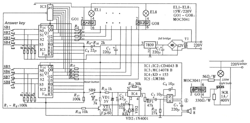
Figure 3: Composition of the eight-channel quiz buzzer circuit
The eight-channel quiz buzzer circuit shown in Figure 3 is designed for use by eight participants. It features interlocking functionality and audio-visual indication. The circuit consists of eight key inputs, interlocking circuit, audio-visual indication circuit, master reset circuit, and power supply circuit.
4. Car voice horn circuit
In Figure 4, the dashed line on the left represents the original car horn circuit, with Sl being the horn button switch on the steering wheel. S2 is a newly added single-pole double-throw switch used for switching between the original car horn and the voice horn. When switch S2 is set to "2" and switch Sl is pressed, capacitor Cl charges. Transistors VT1 and VT2 conduct, causing relay J1 to activate. The normally open contact J1-1 closes and supplies power to the circuit for 15 seconds. ICl is a dedicated voice integrated circuit HL-169A, which operates for 2.8 seconds. Therefore, transistors VT3 and VT4 are used to form a self-excited multi-harmonic oscillator, which outputs a high-level trigger signal every 3 seconds. This triggers ICl to output a voice signal every 3 seconds, which is then amplified by IC2 for audio power amplification and emitted through speaker BL.
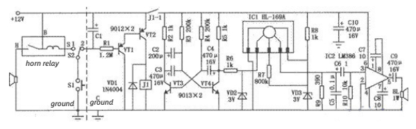
Figure 4: Car voice horn circuit
5. LM386 low-voltage audio power amplifier
LM386 operates with a power supply voltage of 4-12V and provides an audio power of 0.5W. LM386 audio amplifier is manufactured by NSC and has a wide power supply voltage range, with a maximum usage of 15V. It consumes a static current of 4mA. When the power supply voltage is 12V and the load is 8 ohms, it can deliver several hundred mW of power. Its typical input impedance is 50K.

Figure 5: LM386 low-voltage audio power amplifier circuit
6. Power Polarity Conversion Circuit
When the output current of the operational amplifier cannot meet the actual requirements, it cannot be simply used in parallel like a gate circuit. At this time, the general-purpose low-power operational amplifier can be replaced with a power amplifier-type operational amplifier with a larger output current, such as the common TDA2030A. C1 and C2 are decoupling capacitors, and the capacitor C3 connected to the same phase output of the operational amplifier serves to suppress interference and filter. For most OTL power amplifier devices, they generally have a symmetrical bias circuit structure internally, which makes the DC potential at the output terminal approximately half of the power supply voltage. Based on the above principle, we can completely use the integrated operational amplifier to convert a single power supply into equally sized bipolar positive and negative power supplies. The specific circuit is shown in the following figure.
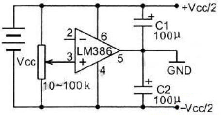
Figure 6: Power Polarity Conversion Circuit composed of LM386
7. Microcomputer Stereo Power Amplifier Circuit
Because the audio signal amplitude of the "line output terminal" of the sound card is too large, it can drive the LM386 to drive the speaker. However, when playing VCD, it will be affected by video signal interference, and the effect of connecting it according to the typical circuit is not good. It is necessary to add some components and adjust the component values. The schematic diagram is shown in Figure 7.
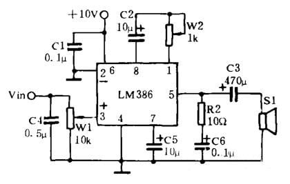
Figure 7: Schematic diagram of the microcomputer stereo power amplifier circuit using LM386
LM386 has two input terminals, the in-phase input terminal (pin 3) and the inverted input terminal (pin 2). The input signal can be input from either terminal, and the other input terminal is grounded. The input terminal is connected in parallel with capacitor C4, which aims to filter out video interference when playing VCD. The value of the capacitor can be appropriately increased, but it can be used with or without C4 when playing CD. Pins 1 and 8 are the gain control terminals, and the gain control network is composed of C2 and W2. The smaller the resistance value, the higher the gain. In the schematic diagram, W2 is adjusted to around 150Ω, which is suitable for the gain. Too high gain may cause self-excitation. Pin 7 is connected to a 10μ capacitor to avoid self-excitation when the gain is too high. R2 and C6 form a high-frequency component attenuation circuit to eliminate the "cracking" sound emitted by the speaker. The capacitance of C6 is adjusted according to the actual effect. Pin 6 is connected to a 0.1μ capacitor to filter out amplifier static AC noise. Pin 5 is connected to coupling capacitor C3. If only one paper cone speaker is connected to one channel (this article uses a paper cone speaker with a diameter of 120mm, an impedance of 8 ohms, and an output power of 1W), the capacitance of C3 should not exceed 470μ, otherwise, the speaker will be blocked when playing heavy bass music. If high and low-frequency division technology is used, the capacitance of C3 can be increased to fully reflect the low-frequency sound. W1 is used to adjust the output volume, which is especially convenient when playing games or listening to CDs. The working voltage is 10V, and a bridge rectifier and filter circuit can be homemade.
Installation and debugging:
According to the schematic diagram shown in Figure 7, make two identical amplifier circuits, and combine them to form a stereo amplifier. Since there are fewer components, it is not necessary to make a printed circuit board. It is recommended to use shielded dual-core wire for the signal line, and connect the stereo plug to the two amplifiers, with the shielded wire serving as the ground wire. After the amplifier is soldered, do not connect it to the sound card first. Check if the soldering is correct, then turn on the power supply, and tap the two input terminals of the stereo plug with a metal tweezer. If both speakers can produce normal tapping sound, it means that the amplifier is working properly. After turning off the amplifier and the computer power, it can be connected to the sound card. The connection method is to plug the stereo plug into the line output jack of the sound card, such as the SoundBlasterPro16 sound card. There are four jacks from top to bottom: headphone or passive speaker jack, line output jack, line input jack, and microphone input jack. For other brands of sound cards, please refer to the manual to find the line output jack and plug it in.
Finally, it is emphasized that it is necessary to avoid plugging or unplugging the stereo plug with a powered computer or amplifier, or soldering the circuit while the amplifier is connected to the sound card to avoid damaging the computer.
8. OCL Power Amplifier Circuit
Circuit working principle: IC1 and IC2 in the circuit are two integrated operational amplifiers LM386 connected in an OCL circuit. C1 acts as a power supply filter and decoupling capacitor, and C3 is the input coupling capacitor. R1 and C2 prevent self-excitation of the circuit, and RP is the static balance adjustment potentiometer. IC1 and IC2 use the integrated operational amplifier circuit LM386, which has the characteristics of low power consumption, wide voltage adaptation range, wide frequency response range, and fewer peripheral components. Its operating voltage is 4V to 16V. When the working voltage in the figure is 6V, the rated output power can reach 3W, which is suitable for driving small speakers or as a voice prompt and alarm amplifier for devices. Resistor R uses a 1/2W metal film resistor. Capacitor C1 uses an electrolytic capacitor with a withstand voltage of 16V; C2 uses a polypropylene capacitor, and C3 uses a tantalum electrolytic capacitor. RP uses an organic solid core potentiometer. Speaker BL should be selected according to actual needs, with an impedance of 8Ω and a rated power below 10W.
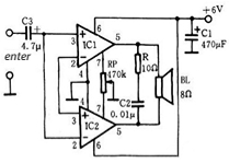
Figure 8: Circuit diagram of the OCL power amplifier circuit composed of LM386
Production and debugging method: After the circuit is installed, ground the audio signal input terminal and adjust RP to make the DC output voltage of the two 5th pins of IC1 and IC2 equal. Since LM386 has fewer external components, it can generally work properly under normal circumstances. The circuit can be installed on a homemade printed circuit board or soldered on a universal printed circuit board.


Company
About UsContact UsTerms & ConditionsPrivacy StatementPayment,Shipping & InvoiceRefund & Return PolicyWarranty PolicyFrequently asked questionHolidays for Chinese Mid-Autumn Festival and National Day in 2023 Copyright © 2022-2024 Power by Chipdatas Trading Limited. All Rights Reserved.