- Deliver to
 USLanguageEnglish


Enter the order reference number received by email to check the status or make payment.
 Purchase Protection
Powerful Protection from Payment to Delivery
Secure and Reliable Payment
Money Back Guarantee
Shipping and Delivery
After-Sales Service
Understanding Different Types of LCD Interfaces
There are various types of LCD interfaces available, each with a wide range of applications. The classification of these interfaces is primarily based on the driving mode and control mode of the LCD. Currently, there are several connection modes commonly used for color LCDs in mobile phones, including MCU mode, RGB mode, SPI mode, VSYNC mode, MDDI mode, and DSI mode. It's important to note that only the TFT module supports the RGB interface.
1. LCD Interface Modes
The following is a detailed explanation of the different interface modes:
1.1 MCU Mode
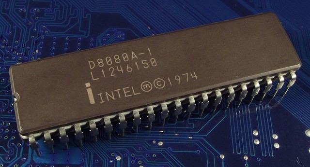
MCU Mode is primarily used in single-chip microcomputers and low-end mobile phones due to its affordability. The standard term for the MCU-LCD interface is the 8080 bus standard proposed by Intel. The MCU-LCD screen is often referred to as "8080" in many documents. It can be divided into 8080 mode and 6800 mode, with the main difference being the timing. Data bit transfer can be 8 bits, 9 bits, 16 bits, 18 bits, or 24 bits. The connections include CS/ (chip select), RS (register selection), RD/ (read), WR/ (write), and data lines. The advantages of MCU mode are simple and convenient control without the need for clock and synchronization signals. However, it consumes GRAM, making it difficult to achieve large screens (above 3.8 inches). The internal chip of an MCU interface LCD module is called the LCD driver, which converts the data/command sent by the host into RGB data for each pixel to be displayed on the screen. This process does not require point, line, or frame clocks.
1.2 VSYNC Mode
VSYNC Mode adds a VSYNC signal to the MCU mode and is used for updating moving pictures. This mode supports direct animation display with minimal changes to the MCU interface. The internal display operation is synchronized with the external VSYNC signal, allowing for animation display at a higher rate than internal operations. However, this mode has a speed limit, as the write speed to the internal SRAM must be faster than the display read speed from the internal SRAM.
1.3 M6800 Mode
The M6800 mode supports selectable bus widths of 8/9/16/18 bits (default is 8 bits). The design idea is similar to the Intel 8080 mode, with the main difference being the bus control read and write signals. These signals are combined on one pin and include a latch signal (E) for data bit transmission of 8, 9, 16, or 18 bits.

1.4 Intel 8080 Mode
The Intel 8080 LCD interface includes CS/ (chip select), RS (register selection), RD/ (read), WR/ (write), and data lines. The advantages of this mode are simple and convenient control without the need for clock and synchronization signals. However, it consumes GRAM, making it difficult to achieve large screens (above QVGA resolution).

1.5 RGB Mode
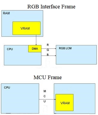
RGB Mode is commonly used for larger screens and supports data bit transmission of 6, 16, 18, or 24 bits. The connections generally include VSYNC, HSYNC, DOTCLK, CS, RESET, and sometimes RS, along with the data lines. The advantages and disadvantages of RGB Mode are the opposite of MCU Mode. The main difference between MCU-LCD and RGB-LCD screens is the location of the video memory. RGB-LCD uses system memory as the video memory, allowing for larger screen sizes limited only by the system memory size. The display update speed of RGB-LCD is significantly faster than that of MCU-LCD. In RGB Mode, the host directly outputs RGB data for each pixel without conversion, requiring an LCD controller in the host part to generate RGB data and sync signals.
1.6 SPI (Serial Peripheral Interface) Mode
SPI Mode is less commonly used and can be implemented with either 3-wire or 4-wire connections. The connections include CS/ (chip select), SLK (serial clock), SDI (serial data input), and SDO (serial data output). Software control for SPI Mode is more complicated compared to other modes.
1.7 MDDI (Mobile Display Digital Interface) Mode
MDDI, developed by Qualcomm, improves the reliability and reduces power consumption of mobile phones by reducing wiring. It is expected to replace SPI Mode as a high-speed serial interface in the mobile field. The main connections in MDDI Mode include host_data, host_strobe, client_data, client_strobe, power, and GND.
1.8 DSI (Display Serial Interface) Mode
DSI Mode is a bidirectional high-speed serial command transmission mode. It uses connections such as D0P, D0N, D1P, D1N, CLKP, and CLKN.
2. MCU Mode vs RGB Mode
Among the different modes of operation, the MCU mode and RGB mode are the most commonly used. Let's take a closer look at the differences between these two modes:
2.1 MCU interface: In this mode, the display commands are decoded, timing signals are generated by the timing generator, and the COM (Common) and SEG (Segment) lines are driven.
RGB interface: In terms of writing LCD register settings, the RGB interface is similar to the MCU interface. The main difference lies in how the image is written.
2.2 When using the MCU mode, data can be stored in the internal GRAM (Graphics RAM) of the IC (Integrated Circuit) before being written to the screen. This allows the LCD to be directly connected to the memory bus. On the other hand, the RGB mode does not have internal RAM. In this mode, the HSYNC, VSYNC, ENABLE, CS, RESET, and RS signals can be directly connected to the GPIO (General Purpose Input/Output) port of the memory, and the GPIO port can be used to simulate waveforms.
2.3 MCU Interface vs RGB Interface:
The main differences between the MCU interface and the RGB interface are as follows:
- MCU interface mode: In this mode, the display data is written into DDRAM (Display Data RAM). It is commonly used for displaying still pictures.
- RGB interface mode: In this mode, the display data is not written into DDRAM. Instead, it is directly written to the screen. This mode is faster and is often used for displaying videos or animations.
3. TFT-LCD Interface Explained
The commonly used interfaces of TFT-LCD, including TTL (RGB), LVDS, EDP, and MIPI, have different signal composition principles. Let's discuss each interface in detail.
3.1 TTL Interface
1. Interface Overview
TTL stands for transistor-transistor logic and is used to generate TTL level signals using TTL devices. TTL devices are a category of digital integrated circuits manufactured using bipolar technology. They are known for their high speed, low power consumption, and wide variety.
The TTL interface is used for parallel data transmission. It does not require dedicated interface circuits at the driver board and LCD panel ends of the liquid crystal display. Instead, the TTL data signal output by the main control chip of the driver board is directly transmitted to the input interface of the LCD panel through a cable. However, due to the high signal voltage, multiple connections, and long transmission cables involved in the TTL interface, the circuit has relatively poor anti-interference ability and is susceptible to electromagnetic interference (EMI). In practical applications, TTL interface circuits are mostly used for driving small-sized (below 15 inches) or low-resolution LCD panels. The highest pixel clock of the TTL interface is only 28MHz.
TTL is the only signal that TFT-LCD can recognize. Early digital processing chips directly output RGB signals to TFT-LCD using TTL.
2. Signal Types
The TTL output interface of the driver board generally includes three types of signals: RGB data signal, clock signal, and control signal. Let's discuss them below:
(1) RGB Data Signal
a. Single Channel
- 6-Bit: This configuration has a total of 18 RGB data lines, including 6 red primary color data lines (R0~R5), 6 green primary color data lines (G0~G5), and 6 blue primary color data lines (B0~B5). It is also referred to as the 18-bit TTL interface since the primary color RGB data is 18 bits.
- 8-Bit: This configuration has a total of 24 RGB data lines, including 8 red primary color data lines (R0~R7), 8 green primary color data lines (G0~G7), and 8 blue primary color data lines (B0~B7). It is also referred to as the 24-bit TTL interface since the primary color RGB data is 24 bits.
b. Dual Channel
Dual channels refer to two sets of RGB data, which are divided into odd channels and even channels. Some clocks are also divided into OCLK/ECLK, while some share one clock. The following figure illustrates this configuration:
- 6-Bit: This configuration has a total of 36 RGB data lines, including 18 odd RGB data lines and 18 even RGB data lines. It is also referred to as the 36-bit TTL interface since the primary color RGB data is 36 bits.
- 8-Bit: This configuration has a total of 48 RGB data lines, including 24 odd RGB data lines and 24 even RGB data lines. It is also referred to as the 48-bit TTL interface since the primary color RGB data is 48 bits.
(2) Clock Signal
The clock signal refers to the pixel clock signal, which serves as a reference for transmitting and reading the data signal. When transmitting RGB data using the odd/even pixel dual method, different output interfaces use different pixel clock methods. Some output interfaces share a pixel clock signal for odd/even pixel dual data, while others have separate clock signals for odd and even pixels to meet the requirements of different LCD panels.
(3) Control Signal
The control signals include a data enable signal (or effective display data strobe signal) DE, a horizontal sync signal HS, and a vertical sync signal VS.
3.2 LVDS
1. Overview of LVDS Interface
LVDS stands for low-voltage differential signaling and is a technology interface used for transmitting digital video signals. It was developed to overcome the drawbacks of high power consumption and electromagnetic interference (EMI) associated with transmitting high bit rate data in TTL level mode. The LVDS output interface uses a very low voltage swing (around 350mV) to differentially transmit data on two PCB traces or a pair of balanced cables. This technology enables high-speed data transmission at several hundred megabits per second with low noise and low power consumption.
2. Composition of LVDS Interface Circuit
In a liquid crystal display, the LVDS interface circuit consists of two parts: the LVDS output interface circuit (LVDS transmitter) on the motherboard side and the LVDS input interface circuit (LVDS receiver) on the LCD panel side. The LVDS transmitter converts the TTL signal into an LVDS signal and transmits it to the LVDS decoding IC on the receiving end through a flexible cable. The LVDS receiver then converts the serialized LVDS signal into a parallel TTL level signal and sends it to the LCD screen timing control and row/column drive circuit. In other words, TFT-LCD panels only recognize TTL (RGB) signals.
3. Signal Types of LVDS Interface
LVDS signals consist of data differential and clock differential signals. Let's discuss the signal types for single-channel and dual-channel configurations:
(1) Single Channel
- 6-Bit Data: This configuration has 4 sets of differential lines, including Y0M, Y0P, Y1M, Y1P, Y2M, Y2P, CLKOUT_M, CLKOUT_P.
- 8-Bit Data: This configuration has 5 sets of differential lines, including Y0M, Y0P, Y1M, Y1P, Y2M, Y2P, CLKOUT_M, CLKOUT_P.
(2) Dual Channel
When transmitting data with higher resolution, LVDS has stronger anti-interference ability. However, when the resolution exceeds 1920×1080, a single channel is insufficient, so a dual interface is used to increase speed and enhance anti-interference ability. Let's discuss the signal types for 6-bit and 8-bit data configurations:
- 6-Bit Data: This configuration is exactly twice as long as the single channel, and the clock is also transmitted through two channels. The red part of the signal includes two sets of signals: Y3M, Y3P, Y3M1, and Y3M1 (not connected).
- 8-Bit Data: This configuration is similar to the previous comparison.
3.3 EDP (Embedded Display Port)
EDP is a communication interface used for computer display screens. It supports higher resolutions compared to the LVDS interface and is commonly used for high-definition screens. EDP is a fully digital interface based on the DisplayPort architecture and protocol. It enables the transmission of high-resolution signals using simpler connectors and fewer pins, resulting in a much higher transmission rate than LVDS.
3.4 MIPI Interface
The MIPI interface, although less common than the LVDS interface, offers several advantages. The MIPI interface module provides high-speed and large-volume data transmission, low power consumption, and excellent anti-interference capabilities compared to parallel port interfaces. It is increasingly favored by customers and is growing rapidly. For example, an 8M module with both MIPI and parallel port transmission requires at least 11 transmission lines and an output clock of up to 96M to achieve a full pixel output of 12 frames per second (FPS) using an 8-bit parallel port. On the other hand, using 6 transmission lines in the MIPI interface can achieve a frame rate of 12 FPS at full pixels, with a lower current consumption of approximately 20mA compared to parallel port transmission. Since MIPI uses differential signal transmission, the design needs to strictly adhere to the general rules of differential design, particularly achieving differential impedance matching. The MIPI protocol specifies a differential impedance of 80-125 ohms for transmission lines.
4. FAQ
1. What is an LCD interface?
A 16x2 LCD refers to a liquid crystal display with two rows that can display 16 characters per line. Each character occupies a 5x7 matrix space on the LCD. In this tutorial, we will be connecting a 16x2 LCD module to the 8051 microcontroller (AT89S52).
2. What is an LCD parallel interface?
LCD displays that use a parallel interface include character, graphic, and TFT displays. The first step is to power up the LCD. Reads and writes are sent through 8 data lines and 3 control lines. These control lines are Read/Write (R/W), Enable (E), and Register Select (RS).
3. What is a TFT interface?
A TFT LCD display module consists of a TFT LCD panel, one or more COG (chip-on-glass) or COB (chip-on-board) driver ICs, a backlight, and an interface. There are several TFT display interface technologies available today. The choice of interface depends on specific end-product requirements.
4. What are the different types of LCDs?
There are several different types of LCD panels:
- Twisted Nematic (TN): Twisted Nematic LCDs are the most commonly manufactured and used types of monitors in various industries.
- IPS Panel Technology: IPS panels offer improved color reproduction and wider viewing angles compared to TN panels.
- VA Panel: VA panels provide better contrast and color accuracy, making them suitable for applications that require high image quality.
- Advanced Fringe Field Switching: AFFS panels offer enhanced viewing angles and outdoor visibility.
5. What is an MCU interface?
The MCU interface has two standard types: the Intel-8080 and Motorola-6800 series. These interfaces communicate through read, write, and chip-select signals to address registers or display RAM. The slight difference between the two lies in the direction and separation of the write and read signals.
6. What is an MCU interface LCD?
An MCU interface LCD communicates through read, write, and chip-select signals to address registers or display RAM. Depending on the color depth (8, 9, 16, or 18-bit), the MCU sends RGB signals directly to the LCD module's display memory.
7. Is TFT an LCD?
Yes, TFT is a type of LCD. TFT (Thin Film Transistor) is a technology in which each pixel in the liquid crystal display is controlled by a thin film transistor embedded behind it. This allows for high-speed, high-brightness, and high-contrast display of screen information.


Company
About UsContact UsTerms & ConditionsPrivacy StatementPayment,Shipping & InvoiceRefund & Return PolicyWarranty PolicyFrequently asked questionHolidays for Chinese Mid-Autumn Festival and National Day in 2023 Copyright © 2022-2024 Power by Chipdatas Trading Limited. All Rights Reserved.