


 Purchase Protection
Powerful Protection from Payment to Delivery
Secure and Reliable Payment
Money Back Guarantee
Shipping and Delivery
After-Sales Service
Enter the order reference number received by email to check the status or make payment.
Top 10 Electronic Components Inventory
As practitioners in the electronics industry, we have a special emotional attachment to various electronic components. For electronic engineers, electronic components are as essential as rice in daily diet, and they need to be in contact with and used every day. However, not all engineers are familiar with the knowledge and technology inside these components. Therefore, this article will list the top ten electronic components most commonly used by engineers in the electronics industry, and introduce related basic concepts and knowledge, hoping to help everyone review them again.
1. Resistance
As one of the most commonly used components in the electronics industry, resistors play an important role in circuits. Their functions include impeding the flow of current, regulating voltage and power in circuits, protecting components in circuits, generating signal waveforms, and filtering.
The resistance value of a resistor can be indicated by three methods: direct marking, color coding, and numerical marking. Among them, color coding is the most commonly used method. The parameter of resistance is generally measured in ohms (Ω), and can also be expressed in multiples such as kilohms (KΩ) and megohms (MΩ).
In circuit design, we need to choose suitable resistor components according to specific requirements, and pay attention to parameters such as accuracy, stability, and temperature coefficient. At the same time, we also need to consider factors such as the size, installation method, and price of resistor components.
It is worth noting that the resistance value of a resistor is generally related to temperature, and the temperature coefficient is a physical quantity that measures the degree of resistance affected by temperature. It is defined as the percentage of change in resistance value per degree Celsius of temperature increase. Therefore, it is necessary to consider the temperature coefficient of resistors in circuit design to ensure the stability and reliability of the circuit.
As one of the most basic and commonly used components in the electronics industry, the importance of resistors is self-evident. In circuit design and application, we need to understand the basic principles and parameters of resistors to ensure the normal operation and performance optimization of circuits.

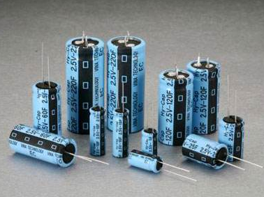
2. Capacitance
Capacitance, also known as capacitance or capacitance value, refers to the amount of charge stored at a given potential difference. It is denoted by the symbol C and its international unit is the Farad (F). In general, when charges are present in an electric field, they will move as a result of the force exerted on them. However, when there is a dielectric material between conductors, this will impede the movement of charges and cause them to accumulate on the conductors. This accumulation of charge storage is most commonly seen in parallel metal plates, which are also known as capacitors.
1. In electronic circuits, capacitors are generally represented by the letter "C" followed by a number (e.g. C13 represents capacitor number 13). Capacitors are made up of two metal plates that are separated by an insulating material. The main characteristic of a capacitor is its ability to block direct current and allow alternating current to pass through. The capacitance of a capacitor indicates the amount of electrical energy it can store, and its impedance to AC signals is known as capacitive reactance, which depends on the frequency of the AC signal and the capacitance value. Common types of capacitors used in telephones and other electronic devices include electrolytic capacitors, ceramic capacitors, surface mount capacitors, monolithic capacitors, tantalum capacitors, and polyester capacitors. For more information, please visit the website of the Electrical Power Equipment Network.
2. Capacitors can be identified using three methods: direct marking, color coding, and numerical coding. The basic unit of capacitance is the Farad (F), and other units include millifarads (mF), microfarads (uF), nanofarads (nF), and picofarads (pF). For example, 1 Farad = 1,000 millifarads = 1,000,000 microfarads = 1,000,000,000 nanofarads = 1,000,000,000,000 picofarads. The capacitance value of larger capacitors can be directly marked on the capacitor, while smaller capacitors may be marked with letters or numbers. Letter codes include 1m = 1000uF, 1P2 = 1.2pF, and 1n = 1000pF. Numeric codes typically use three digits to indicate the capacitance value, with the first two digits representing the significant figures and the third digit indicating the multiplier. For example, 102 represents 10 x 102 pF = 1000 pF, and 224 represents 22 x 104 pF = 0.22 uF.
3. Capacitance tolerance is represented by the symbols FGJKLM, which allow for a tolerance of ±1%, ±2%, ±5%, ±10%, ±15%, or ±20%. For example, a ceramic capacitor marked 104J indicates a capacitance of 0.1 uF with a tolerance of ±5%.
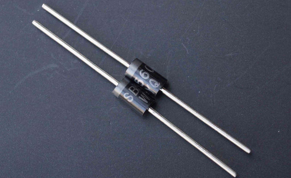
3. Crystal Diode
The crystal diode is a solid-state electronic device with two semiconductor terminals. These devices are mainly characterized by their nonlinear current-voltage characteristics. With the development of semiconductor materials and process technology, a variety of crystal diodes with different semiconductor materials, doping distributions, and geometric structures have been developed, which have various functions and uses. The materials used for manufacturing include germanium, silicon, and compound semiconductors. Crystal diodes can be used to generate, control, receive, transform, amplify signals, and perform energy conversion.
Crystal diodes are commonly represented by the letter "D" followed by a number in electronic circuits, such as D5 for diode number 5.
1. Function: The main characteristic of a diode is its unidirectional conductivity, that is, under the action of forward voltage, the conductive resistance is very small, while under the action of reverse voltage, the conductive resistance is extremely large or infinite. Because of the above characteristics, crystal diodes are commonly used in rectification, isolation, voltage stabilization, polarity protection, encoding control, frequency modulation, and noise reduction circuits in cordless telephones. The crystal diodes used in telephones can be divided into rectifying diodes (such as 1N4004), isolation diodes (such as 1N4148), Schottky diodes (such as BAT85), light-emitting diodes, voltage-stabilizing diodes, etc.
2. Identification method: The identification of diodes is very simple. The N-pole (negative pole) of small power diodes is mostly marked with a color ring on the surface of the diode. Some diodes also use special symbols to indicate the P-pole (positive pole) or N-pole (negative pole), and some diodes use the symbols "P" and "N" to determine the polarity of the diode. The positive and negative poles of the light-emitting diode can be identified by the length of the pins, with the longer pin being the positive pole and the shorter pin being the negative pole.
3. Testing precautions: When using a digital multimeter to test a diode, the red test lead should be connected to the positive pole of the diode, and the black test lead should be connected to the negative pole of the diode. At this time, the measured resistance value is the forward conduction resistance value of the diode, which is opposite to the test lead connection method of a pointer multimeter.
4. The voltage withstand comparison of the commonly used 1N4000 series diodes is as follows: Type 1N4001 1N4002 1N4003 1N4004 1N4005 1N4006 1N4007 Voltage withstand (V) 50 100 200 400 600 800 1000 The current (A) is 1 for all.
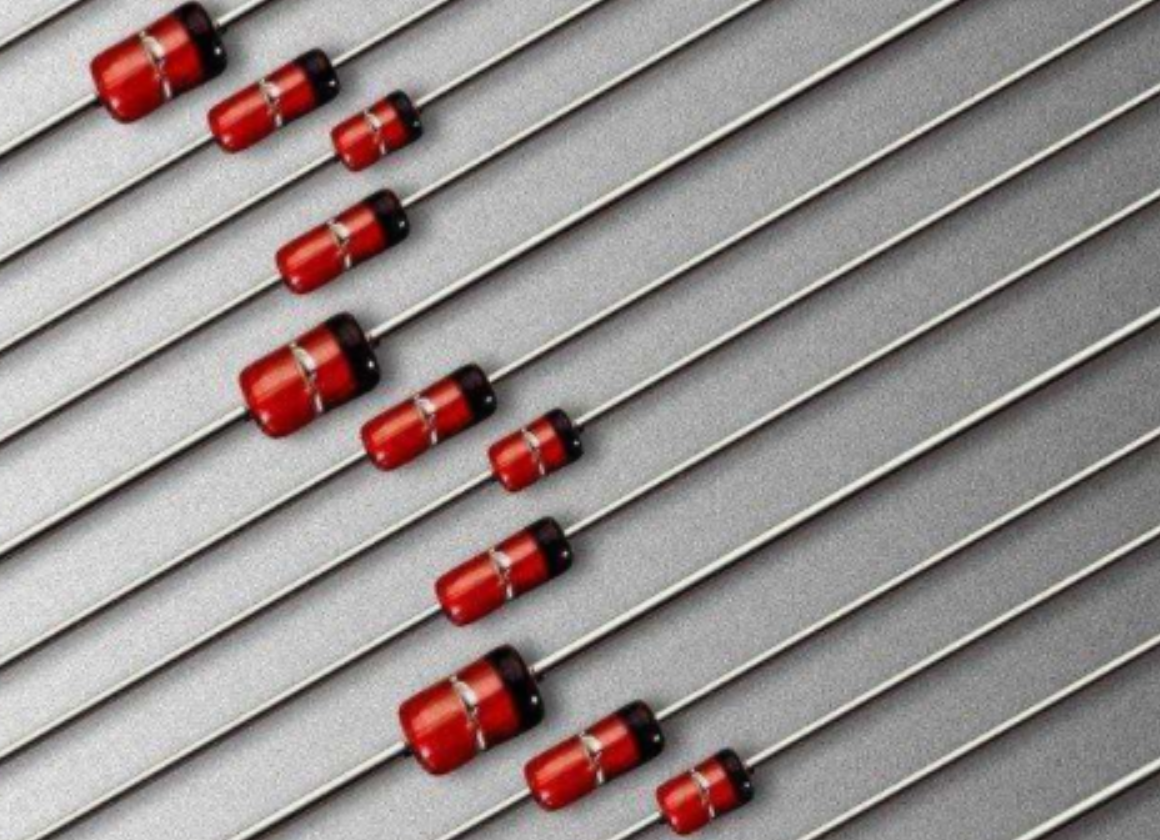
4. Zener Diode
Zener diodes, also known as voltage regulator diodes, are a type of semiconductor device. Their characteristic is that when a certain reverse voltage is reached, the current sharply increases, causing the voltage to stabilize at a fixed value.
Zener diodes are usually represented by "ZD" followed by a number, for example ZD5 represents voltage regulator diode number 5.
The principle of voltage regulation for Zener diodes is simple: when the reverse voltage of the Zener diode reaches a critical value, the current sharply increases, thus keeping the voltage at its two ends basically unchanged. Therefore, when the voltage regulator diode is connected to a circuit, even if the power supply voltage fluctuates or other reasons cause voltage changes at various points in the circuit, the voltage at both ends of the load will remain basically unchanged.
The faults of Zener diodes are mainly manifested in open circuit, short circuit, and unstable voltage regulation values. Among them, open circuit faults are manifested as an increase in power supply voltage, while short circuit faults and unstable voltage regulation faults are manifested as a decrease in power supply voltage to zero volts or unstable output.
The commonly used Zener diode models and their voltage regulation values are listed in the following table:
| Model | Regulator value |
|---|---|
| 1N4728 | 3.3V |
| 1N4729 | 3.6V |
| 1N4730 | 3.9V |
| 1N4732 | 4.7V |
| 1N4733 | 5.1V |
| 1N4734 | 5.6V |
| 1N4735 | 6.2V |
| 1N4744 | 15V |
| 1N4750 | 27V |
| 1N4751 | 30V |
| 1N4761 | 75V |
5. Inductance
Inductance is an electrical component that consists of an insulated wire wound into a coil. When a current flows through the coil, it generates a magnetic field within the coil, which in turn generates an induced current to resist the current flowing through the coil. This interaction between the current and the coil is known as electrical reactance, or inductance, which is measured in Henrys (H). Inductance can be used to manufacture inductive components.
In circuits, inductance is typically denoted by the letter "L" followed by a number, such as L6 for inductance number 6. An inductance coil is made by winding an insulated wire around an insulated frame. When a direct current flows through the coil, the resistance is simply the resistance of the wire itself, resulting in a small voltage drop. However, when an alternating current signal passes through the coil, the coil generates a self-induced electromotive force, which opposes the direction of the applied voltage and impedes the flow of the alternating current. Thus, the characteristics of inductance are that it allows direct current to pass through while blocking alternating current, and the higher the frequency, the greater the coil impedance. Inductance can be combined with capacitance to form oscillating circuits.
Inductance can be represented using two methods: direct notation and color notation. Color notation is similar to the notation used for resistors. For example, a brown-black-gold-gold band represents a 1uH inductance with a 5% tolerance. The basic unit of inductance is the Henry (H), which can be converted using the following units: 1H = 103mH = 106uH.

6. Varactor Diode
Varactor diodes, also known as variable reactance diodes, are a type of diode made using the principle of the dependence relationship between the PN junction capacitance (barrier capacitance) and its reverse bias voltage Vr. They are a special type of diode, where the internal PN junction capacitance changes with the variation of the reverse bias voltage. Varactor diodes are mainly used in high-frequency circuits to modulate low-frequency signals onto high-frequency signals and transmit them. In the working state, the modulation voltage of the varactor diode is generally applied to the negative pole, causing its internal junction capacitance to change with the modulation voltage.
When varactor diodes fail, they mainly show leakage or performance degradation. When leakage occurs, the high-frequency modulation circuit will not work or the modulation performance will deteriorate. When the varactor's performance deteriorates, the high-frequency modulation circuit's operation will be unstable, resulting in distortion of the high-frequency signal sent to the receiver. In this case, the same model of varactor diode should be replaced.
Varactor diodes are a very important electronic component, and they play an important role in high-frequency circuits such as cordless telephones. Understanding the working principle of varactor diodes and their fault handling methods is of great significance for the maintenance and repair of high-frequency circuits.
7. Transistor
The transistor is a semiconductor device with current amplification function, and is one of the indispensable components in electronic circuits. There are two types of transistors: NPN and PNP, which can complement each other's working characteristics. The transistor is commonly represented in circuits as "Q" plus a number, such as Q17 representing transistor number 17.
Transistors are commonly used to amplify currents in amplification circuits, and there are three common ways to connect them: common emitter, common collector and common base, each with its own characteristics and applicable scenarios. In circuits, transistors have input and output impedance characteristics, and the input and output impedance of different connection methods are different, which will also affect characteristics such as voltage amplification, current amplification and power amplification.
Transistors are widely used in electronic circuits, including multistage amplifiers, low-frequency amplification, high-frequency or wide-band circuits, constant current source circuits, etc. In multistage amplifiers, transistors are commonly used in intermediate stages; in low-frequency amplification, transistors are commonly used in input stages, output stages or for impedance matching; in high-frequency or wide-band circuits, transistors are commonly used to amplify high-frequency signals; in constant current source circuits, transistors are commonly used to generate stable current sources.
8. FET
The Field Effect Transistor (FET), also known as the Field Effect Transistor, is a semiconductor device that operates based on the participation of majority carriers in conduction. It is also known as a unipolar transistor and belongs to the voltage-controlled semiconductor devices. FETs have several advantages, including high input impedance (108-109 Ω), low noise, low power consumption, large dynamic range, easy integration, no secondary breakdown phenomenon, and a wide safe operating area. It has become a strong competitor to bipolar transistors and power transistors.
FETs are widely used in various electronic devices due to their high input impedance and low noise. In particular, using FETs as the input stage of an electronic device can achieve performance that is difficult to achieve with general transistors.
FETs are divided into two types: junction-type and insulated-gate-type, but their control principles are the same. Figure 1-1-1 shows the symbols for the two types.
Compared with transistors, FETs have several differences:
1. FETs are voltage-controlled devices, while transistors are current-controlled devices. When only a small amount of current can be taken from the signal source, FETs should be selected. When the signal voltage is low and a larger amount of current can be taken from the signal source, transistors should be selected.
2. FETs use majority carriers to conduct electricity, so they are called unipolar devices, while transistors use both majority and minority carriers to conduct electricity and are called bipolar devices.
3. Some FETs can interchange the source and drain, and the gate voltage can be positive or negative, making them more flexible than transistors.
4. FETs can work under very small currents and low voltages, and their manufacturing process can conveniently integrate many FETs on a silicon wafer, making them widely used in large-scale integrated circuits.
9. Sensor
A sensor is a physical device or biological organ that can detect and sense signals, physical conditions (such as light, heat, humidity), or chemical composition (such as smoke) of the external environment, and transmit the detected information to other devices or organs. According to the definition of the national standard GB7665-87, a sensor is a detection device that can sense the measured information and can transform the detected information into electrical signals or other required forms of information output according to certain rules, in order to meet the requirements of information transmission, processing, storage, display, recording, and control. The function of a sensor is to convert one form of energy into another form of energy to meet the requirements of automatic detection and automatic control. Therefore, sensors are also known as transducers.
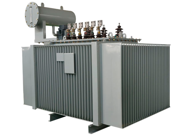
10. Transformer
A transformer is a device that uses the principle of electromagnetic induction to change the voltage of alternating current. It consists of primary coils, secondary coils, and a core (magnetic core). Transformers are commonly used in electrical equipment and wireless circuits for voltage regulation, impedance matching, and safety isolation. In a generator, whether the coil moves through the magnetic field or the magnetic field moves through the fixed coil, an induced electromotive force is generated in the coil. In both cases, the value of the magnetic flux remains unchanged, but the number of magnetic fluxes that intersect with the coil changes, which is the principle of mutual induction. Therefore, transformers can use electromagnetic induction to transform voltage, current, and impedance.
The main functions of transformers include voltage transformation, current transformation, impedance transformation, isolation, and voltage regulation (magnetic saturation transformer). With the voltage transformation function of the transformer, we can convert high voltage to low voltage or low voltage to high voltage to meet the voltage requirements of different electrical equipment. The current transformation function can convert high current to low current or low current to high current to adapt to the power requirements of different electrical equipment. The impedance transformation function can match different impedances to ensure the normal operation of the circuit. The isolation function can prevent electrical interference between electrical equipment and ensure the safety and reliability of the circuit. The voltage regulation function can maintain the stability of the output voltage when the power supply voltage fluctuates.
In summary, transformers are very important electronic devices, and they have a wide range of applications in the power industry, electronics industry, communication industry, and other fields.


Company
About UsContact UsTerms & ConditionsPrivacy StatementPayment,Shipping & InvoiceRefund & Return PolicyWarranty PolicyFrequently asked questionHolidays for Chinese Mid-Autumn Festival and National Day in 2023 Copyright © 2022-2024 Power by Chipdatas Trading Limited. All Rights Reserved.