The role and application scenarios of pull-up resistors and pull-down resistors
As we are all aware, resistors serve a crucial purpose in circuitry by effectively limiting the flow of current. Two commonly mentioned and frequently utilized types of resistors in electronics are pull-up resistors and pull-down resistors. The purpose of a pull-up resistor is to elevate an uncertain signal to a high logical level by employing a resistor as a current limiter. On the other hand, a pull-down resistor is used to lower an uncertain signal to a low logical level. In digital circuits, where there are only two states - high level and low level - the initial stage of digital signals is often characterized by uncertainty.
1. Why Pull-down and Pull-up Resistor?
Pull-up and pull-down resistors play a crucial role in circuitry, particularly when interfacing switches or other inputs with microcontrollers or digital gates. During the initial stage of power-on in a digital circuit, the output state's high and low logical levels are uncertain. To ensure that the circuit state stabilizes, a pull-up resistor or pull-down resistor is necessary.
A pull-up resistor is connected to the positive power supply. When a high voltage is applied to this point, the potential increases. On the other hand, a pull-down resistor is connected to the negative pole, which is also referred to as digital grounding. When the input port signal changes due to different circuit configurations, the change is fed back to the output port. This causes the output port to acquire a state that should have been completed, even though the input port currently has no signal and remains in its original state.
To better understand this concept, let's consider an analogy from daily life. Imagine using a key to open a door. After entering, if the door doesn't close automatically, you can add a switch to make the door close automatically.
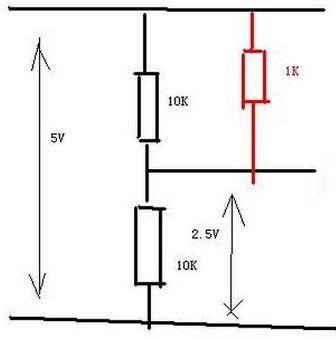
Figure 1
The schematic diagram above (Figure 1) illustrates how the positive input terminal and the pull-up resistor can elevate the level. Assuming the two resistances of the port are equivalent, according to Ohm's law, the voltage of the port is calculated to be 2.5V. By connecting the pull-up resistor (highlighted in red), the voltage of the port increases. In this case, a 10K resistor is connected in parallel with a later connected 1K resistor. The total resistance must be greater than or equal to 1K, resulting in an equivalent series relationship between the 1K resistor and the 10K resistor below. However, the current passing through them remains the same. Consequently, the voltage across the two 10K resistors increases, raising the terminal voltage.
It's important to note that the pin connected to the IC and power (or ground) doesn't necessarily function as a pull-down resistor. This might lead to confusion, as some might assume that the red part in the figure also represents a pull-down resistor. However, it is not connected in series with any pin or ground. In reality, it serves as a circuit startup resistor, not a pull-up/pull-down resistor. Pull-up and pull-down resistors are specifically used for input and output ports. While some circuits may connect pull-up and pull-down resistors to redundant ports for stability, not all resistors are connected to one pin of the IC at all times, with the other pin connected to power or ground to represent the pull-up and pull-down resistors.
2. Pull-up & Pull-down Resistor Circuits
Pull-up and pull-down resistors are essential components in circuitry that help regulate the behavior of signals. Let's delve into their functions and applications in more detail.
In digital circuits, pull-up resistors are used to ensure that a wire or node is pulled to a high logical level when there is no input signal present. On the other hand, pull-down resistors are employed to actively control the voltage between VCC (the positive power supply) and a microcontroller pin.
Let's examine the details further with respect to OC (TTL) and OD (COMS) circuits, as shown in Figure 2.
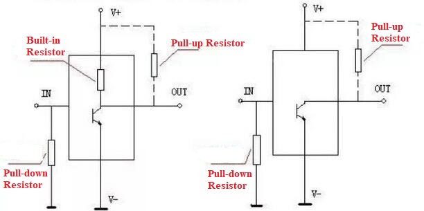
Figure 2
In an OC (TTL) circuit, when the I/O port of the integrated circuit (IC) is in a high logical level, the impedance between the node and the ground (GND) is very large, almost infinite. At this point, a pull-up resistor (such as a 4.7K ohm or 10K ohm resistor) is connected between the node and VCC. The voltage divider effect of the pull-up resistor is negligible in this case. Conversely, when the I/O port node is in a low logical level, it can be directly connected to GND. At this time, VCC and GND are connected through the pull-up resistor, but the current passing through it is very small and can be ignored.
It's important to note that the level values are relative to the ground level. Therefore, whether the pins are connected to peripheral devices is irrelevant to their connection to the ground.
To pull up the potential of a node, a 10K ohm or 4.7K ohm pull-up resistor is commonly used, connected between the node and +5V. This is often done when the node requires control from a microcontroller or other controller (especially when the node is connected to an I/O pin). If the objective is to simply set the node to a high logical level and the output impedance is very high, a direct connection to the power supply can be made. However, if the microcontroller needs to set the node to a low logical level (grounded inside the microcontroller), a connection between the 5V power supply and the ground would create a short circuit.
Additionally, when the node is required to be at a high logical level, the impedance between the node and the ground is generally very high. For example, with an impedance of 100K ohms, connecting a 10K ohm pull-up resistor would result in a voltage at that point of 4.5V, calculated as 100KΩ/(100K +10K)*5V. This setup effectively achieves a high logical level.
Conversely, when the node needs to be at a low logical level, it is directly connected to the ground. However, there is a 10K resistor between the power supply and the ground to prevent a short circuit. In the low state, a loop is formed between the power supply and the ground through the load. Sometimes, this node may be connected in series with a resistor. Since current flows to the path with lower impedance, the current will flow through the resistor connected to the power supply to the ground, bypassing the resistor connected to the node. This is because the resistor connected to the node has a high impedance, resulting in a low potential at that point.
In summary, for the I/O port of an IC, controlling the high and low logical levels inside the IC is equivalent to connecting the I/O port to its internal GND or a very large resistor (e.g., 100K ohms). When the I/O port is in a low logical level (0V), the pin controlling the I/O port of the IC chip is connected to GND inside the chip.
When the I/O port is at a high logical level, such as 5V, the I/O port pin is connected to a very large resistor inside the chip, typically 100K ohms. Sometimes, an additional resistor with a smaller resistance value, such as 68 ohms, may be connected in series at the I/O node. This is because current flows through the path with lower impedance. When the I/O port and GND inside the chip are connected to a low logical level, the pull-up resistor and the GND inside the chip form a loop. At this point, the current at the I/O port node will flow to the GND inside the chip, bypassing the series resistor with higher resistance relative to GND.
To summarize the function of pull-down resistors, they are used when the I/O port is in a high-impedance state. In this state, a pull-down resistor is connected between the port and GND. The high-impedance state can be understood as a disconnection, but in reality, it is a large resistor inside the chip. By connecting the pull-down resistor, the node is pulled to GND, resulting in no current flow and a logical level of 0. Only when a high logical level is applied to this pin can it function as intended.
3. What the Role of Pull-up and Pull-down Resistor?
Pull-up and pull-down resistors play important roles in circuitry, particularly in stabilizing and regulating current flow. Let's further discuss the significance of these resistors.
1) Increasing voltage level:
In certain cases, a pull-up resistor is required to raise the voltage level of a signal. For example, when a TTL circuit drives a CMOS circuit and the TTL's high-level voltage is lower than the CMOS's minimum high-level voltage, a pull-up resistor is connected to the TTL's output terminal to increase the high-level voltage. Similarly, an open-collector (OC) gate circuit needs a pull-up resistor to increase the high-level voltage of the output.
2) Enhancing drive capability:
Pull-up resistors are often employed on certain pins of single-chip devices to improve their drive capability. This helps the device provide a stronger output signal.
3) Anti-static and anti-interference measures:
Unused pins on CMOS chips should not be left floating to prevent damage from static electricity. To address this, a pull-up resistor is connected to reduce input impedance, provide a leakage path, and enhance the chip's resistance to electromagnetic interference. Leaving a pin floating increases its susceptibility to external electromagnetic interference.
4) Resistance matching:
In long-line transmission, resistance mismatch can lead to interference from reflected waves. By using pull-down resistors, resistance matching can be achieved, effectively suppressing reflected wave interference.
5) Presetting default potential:
Pull-up or pull-down resistors are connected to certain CMOS input terminals to preset their default potential. When these pins are not in use, the input terminals are pulled down to a low level or pulled up to a high level. This allows for defining the state of the bus when it is idle, as seen in protocols like I2C, through the use of pull-up and pull-down resistors.
6) Improving noise tolerance:
To prevent random levels in high-impedance or floating input terminals, pull-up or pull-down resistors are added. Similarly, if an output terminal is in a passive state, a pull-down or pull-up resistor may be added. By employing pull-up or pull-down resistors, the noise tolerance of chip input signals can be improved, enhancing their resistance to interference.
4. Pull-up & Pull-down Resistor Applications
When to use pull-up and pull-down resistors? Let's look at several scenarios explained below.
1) Pull-up and pull-down resistors are typically used on input signal pins to fix the signal at a certain level and prevent the signal line from being in an uncertain state. In practical applications, a 10K ohm resistor is the most commonly used pull-up resistor. Whether to use a pull-up or pull-down resistor depends on the requirements of the circuit system itself. For example, for efficient enable control signals, we want the circuit system to be in an inactive state after power-up. In this case, a pull-down resistor can be used.
Let's assume the enable signal is used to control a motor. If the signal line is left floating, other noise interference may accidentally trigger the signal line to a high logic level after power-up (or during operation), causing the motor to rotate unexpectedly. In this case, a pull-down resistor can be added. Similarly, for active low-level reset control signals (RST#), if we want them to be in an inactive state after power-up reset, a pull-up resistor should be used.
2) Most chips with logic control functions, such as microcontrollers and FPGAs, integrate pull-up or pull-down resistors. Users can choose whether to enable them according to their needs. The GPIO mode of the STM32 microcontroller includes pull-up or pull-down resistors.
3) Depending on the resistance value of the pull-up resistor, we can also categorize it as strong pull-up/pull-down and weak pull-up/pull-down. The pull-up resistors integrated in chips are usually weak pull-up (higher resistance). The smaller the pull-up resistor, the stronger the level-driving capability (strong pull-up) and the better resistance to external noise interference (i.e., if unwanted interference noise needs to change the level of a strong pull-up signal, it requires corresponding increased power). However, with a smaller pull-up resistor, the corresponding power consumption is also higher because it takes more energy to change the state of the signal line for normal signals. In terms of power consumption, pull-up and pull-down resistors are the same.
4) There is no strict definition of the critical resistance value between strong pull-up and weak pull-up. Typically, the pull-up resistors we use are weak pull-up, so we can still use external control signals to pull up or pull down the signal line as needed.
The limit value of a strong pull-up resistor is zero, which means the signal line can be directly connected to the power supply or ground.
5) When pull-up resistors are used as outputs (or input and output), more knowledge is involved, but their basic function remains fixing the level. The most common occurrence of output pull-up resistors is in open-drain (OC) or open-drain (OD) structure pins.
6) The sinking ability and sourcing ability of current are also known as the driving capability of chip pins. For any given chip, the driving capability of the pins is limited. If the load driven by a pin is large, it may result in incorrect output levels (unable to output the intended level).
7) The OC (OD) output structure differs (OC structure exists in transistors, while OD structure exists in field-effect transistors, FETs). The outputs of most comparator chips are OD/OC output structures, and the signal pins of many feedback system status chips or modules also have this structure. Therefore, users can pull the level up to the corresponding level according to the actual needs of the circuit system using the power supply voltage VCC, and level conversion can be omitted.
5. How to Select Pull-up & Pull-down Resistor?
When selecting pull-up and pull-down resistors, there are three aspects to consider:
1) Power Saving: To save power, the sink current capability of the chip should be large enough. This means that the resistance value should be large, resulting in a smaller current flowing through the resistor.
2) Drive Current: It is important to ensure sufficient drive current. In this case, the resistance value should be small, allowing a larger current to flow through the resistor.
3) High-Speed Circuits: In high-speed circuits, excessive pull-up resistors can cause smooth edges. Therefore, it is important to choose an appropriate resistance value that does not result in excessive smoothing of the edges.
Taking all these factors into consideration, the resistance value is usually selected between 1K and 10K ohms. This principle also applies to pull-down resistors.
It is worth noting that the pull-up resistors integrated into chips are usually weak pull-ups. The smaller the pull-up resistance, the stronger the level-driving capability, but it also results in higher power consumption. Additionally, output pull-up resistors are commonly found in open-drain (OC) or open-drain (OD) structure pins.
6. FAQ
1. What are pull-up resistors and pull-down resistors?
Pull-up resistors connect unused input pins (in AND and NAND gates) to the DC power supply voltage (Vcc) to maintain a given input at a high level. Pull-down resistors connect unused input pins (in OR and NOR gates) to ground (0V) to maintain a given input at a low level.
2. What is the difference between pull-up resistors and pull-down resistors?
Pull-up resistors connect unused input pins (in AND and NAND gates) to the DC power supply voltage (Vcc) to maintain a given input at a high level. Pull-down resistors connect unused input pins (in OR and NOR gates) to ground (0V) to maintain a given input at a low level.
3. When should pull-up or pull-down resistors be used?
Pull-up and pull-down resistors are commonly used when interfacing switches or other inputs with microcontrollers or other digital gates. Most microcontrollers have built-in programmable pull-up and/or pull-down resistors, so fewer external components are required.
4. What is the purpose of pull-up resistors?
In electronic logic circuits, pull-up resistors (or pull-down resistors) are used to ensure a known state of a signal. They are often used in conjunction with components like switches and transistors, which physically interrupt the connection of subsequent components to ground or VCC.
5. What is the purpose of pull-down resistors?
Similar to pull-up resistors, pull-down resistors ensure that the voltage between VCC and the microcontroller pin is in an actively controlled state when a switch is open. However, these resistors pull the pin towards a low level instead of a high level.
6. How do you calculate the value of a pull-down resistor?
Calculating the value of a pull-down resistor is slightly different from calculating the value of a pull-up resistor. Assuming a current of 100uA, we take 0.5V as the pull-down voltage since the input voltage is 0.8V. So, we apply the same formula R = V/I, but this time we don't subtract the values, so the formula remains the same.
7. Why is a pull-up resistor needed for I2C?
As discussed in the I2C Basics module, the common I2C circuit includes pull-up resistors placed between the SCL and SDA lines and the power supply. Pull-up resistors are used to provide a default state for the signal lines or general-purpose input/output (GPIO) pins.
8. Which port does not have built-in pull-up resistors?
Input/output (I/O) pins - all the circuits in a microcontroller must be connected to one of the pins, except for the P0 port, which does not have built-in pull-up resistors.
9. What are the pull-up and pull-down in Arduino?
Introduction: Understanding pull-up/pull-down resistors in Arduino. Using a pull-up resistor and an unpressed button can make the logic state ON, while pressing the button can make the logic state OFF. Using a pull-down resistor and a pressed button can make the logic state ON, while unpressed makes it OFF.
10. What happens if the pull-up resistor for an I2C signal is too small?
If the value of the pull-up resistor is too small, the output driver will not be able to sink enough current to pull the pin to 0.


Company
About UsContact UsTerms & ConditionsPrivacy StatementPayment,Shipping & InvoiceRefund & Return PolicyWarranty PolicyFrequently asked questionHolidays for Chinese Mid-Autumn Festival and National Day in 2023 Copyright © 2022-2024 Power by Chipdatas Trading Limited. All Rights Reserved.