- Deliver to
 USLanguageEnglish


Enter the order reference number received by email to check the status or make payment.
 Purchase Protection
Powerful Protection from Payment to Delivery
Secure and Reliable Payment
Money Back Guarantee
Shipping and Delivery
After-Sales Service
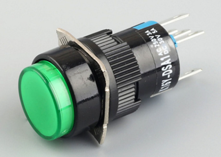
The principle, wiring method and application scenarios of push button switch
The principle of a button switch is to use a button to push the transmission mechanism, so that the movable contact and the stationary contact can be connected or disconnected, thereby switching the circuit. It is a simple and widely used main control electrical appliance, used in electrical automatic control circuits to manually send control signals to control contactors, relays, electromagnetic starters, etc.
A button switch can perform basic controls such as start, stop, forward and reverse rotation, speed control, and interlocking. Typically, each button switch has two pairs of contacts, each pair consisting of a normally open contact and a normally closed contact. When the button is pressed, both pairs of contacts act simultaneously, with the normally closed contact opening and the normally open contact closing.
To indicate the different functions of different buttons and avoid incorrect operations, different colored button caps are usually used for differentiation. For example, red represents the stop button, green represents the start button, etc. The parameters, models, installation hole sizes, number of contacts, and current capacity of the button switch are detailed in the product manual.
There are various types of button switches, so the wiring methods are also not uniform, and there will be various situations. Here are several common button switch wiring problems and their solutions:
1. Wiring problem for button switch with indicator light: If there are five terminals on the button, two of them are for connecting the light, and the other three are for the switch. Find out the terminals for connecting the light and the terminals for the switch, and then determine which two terminals to use for connecting the switch. Connect the light and the desired switch terminal in series. This way, when the switch is turned on, the light will also illuminate.
2. Wiring problem for button switch on the control cabinet: This type of button switch usually has normally open and normally closed contacts, totaling four terminals. As a switch input, the normally closed contact is usually connected to one input point of the PLC (usually the I terminal of the PLC), and the other end is connected to 24V+ of the PLC. The normally open contact remains unconnected.
3. Wiring problem for one switch controlling three lights: For this situation, the switch has three rows of terminals. The first row is L1a, L1b, L1c, the second row is L0a, L0b, L0c, and the third row is L2a, L2b, L2c. Four wires are needed to complete the wiring. One power wire is connected to the incoming terminals of the three switches (L0A, L0B, L0C), and the remaining three wires are connected to L2A, L2B, L2C respectively. If there are only three wires, the yellow wire may be the incoming wire, the white wire is the circuit wire for two lights, and the empty terminal indicates that the switch does not control any light.
I hope the above answers are helpful to you. If you have any other questions, please feel free to ask.


Company
About UsContact UsTerms & ConditionsPrivacy StatementPayment,Shipping & InvoiceRefund & Return PolicyWarranty PolicyFrequently asked questionHolidays for Chinese Mid-Autumn Festival and National Day in 2023 Copyright © 2022-2024 Power by Chipdatas Trading Limited. All Rights Reserved.