


 Purchase Protection
Powerful Protection from Payment to Delivery
Secure and Reliable Payment
Money Back Guarantee
Shipping and Delivery
After-Sales Service
Enter the order reference number received by email to check the status or make payment.
The principle and identification method of Zener diode
This article will introduce the circuit principle and identification methods of the voltage regulator diode. The voltage regulator diode, also known as the Zener diode, utilizes the reverse breakdown phenomenon of the pn junction, where the current can vary greatly while the voltage remains essentially constant. The diode made from this can function as a voltage regulator. The voltage regulator diode has a high resistance, maintaining a high resistance until the critical reverse breakdown voltage. At the critical breakdown point, the reverse resistance decreases to a small value, and in this low-resistance region, the current increases while the voltage remains constant. Due to this characteristic, the voltage regulator diode is mainly used as a voltage stabilizer or voltage reference element. Voltage regulator diodes can be connected in series for use at higher voltages, and through serial connection, a higher stable voltage can be obtained.
Circuit principle of the voltage regulator diode
The voltage regulator diode is connected in parallel with the load, and when the load voltage changes, the current in the voltage regulator diode will automatically adjust, thereby maintaining a stable output voltage. If the mains voltage rises, the output voltage of the rectifier circuit also increases, causing the load voltage to increase. Since the voltage regulator diode is connected in parallel with the load, the current increases sharply, offsetting the increase in output voltage, thereby maintaining the load voltage essentially constant. Conversely, if the mains voltage decreases, the output voltage also decreases, and the current in the voltage regulator diode decreases sharply, offsetting the decrease in output voltage, thereby maintaining the load voltage essentially constant. If the load current increases, the current in the voltage regulator diode will quickly decrease, maintaining a stable output voltage.
The voltage regulator diode plays the role of automatic current regulation, while the current-limiting resistor plays the role of voltage adjustment. The smaller the dynamic resistance of the voltage regulator diode, the larger the current-limiting resistor, and the better the stability of the output voltage.
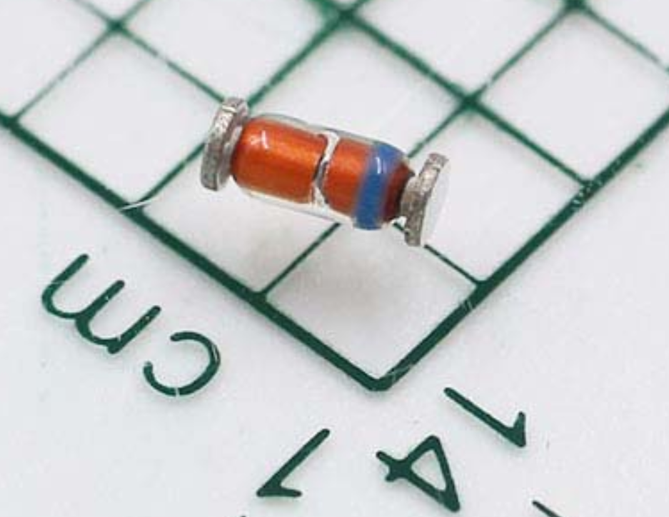
Identification methods of the voltage regulator diode
The voltage regulator diode is commonly represented in circuits by "ZD" followed by a number, such as ZD1 representing voltage regulator diode number 1. The positive end of the metal-encapsulated voltage regulator diode is flat, while the negative end is semi-circular. The plastic-encapsulated voltage regulator diode has a colored marking on one end representing the negative end, while the other end represents the positive end. For voltage regulator diodes with unclear markings, a multimeter can be used to determine their polarity, and the measurement method is the same as that for ordinary diodes.
Distinguishing from ordinary rectifier diodes
First, use a multimeter R×1K range to determine the positive and negative electrodes of the diode being tested. Then, switch the multimeter to the R×10K range, connect the black test lead to the negative end of the diode being tested, and connect the red test lead to the positive end of the diode being tested. If the measured reverse resistance value is much smaller than the reverse resistance measured using the R×1K range, the diode being tested is a voltage regulator diode. Otherwise, if the measured reverse resistance value is still large, the diode is an ordinary rectifier diode or detector diode.


Company
About UsContact UsTerms & ConditionsPrivacy StatementPayment,Shipping & InvoiceRefund & Return PolicyWarranty PolicyFrequently asked questionHolidays for Chinese Mid-Autumn Festival and National Day in 2023 Copyright © 2022-2024 Power by Chipdatas Trading Limited. All Rights Reserved.