Resistor Configurations: Series vs. Parallel
Individual resistors can be commonly connected to three types of circuits: series, parallel, or a combination of series and parallel connections. These connections can form more complex resistor networks, where the equivalent resistance is determined by the mathematical combination of the individual resistors.
A resistor is a fundamental electronic component that serves multiple purposes. It can be used to convert a voltage to a current or vice versa. Additionally, by adjusting its value, a resistor can be utilized to place a different weighting on the converted current and/or voltage. This property makes resistors suitable for voltage reference circuits and various applications.
In certain cases, a single equivalent resistor can replace a series of resistors or a complicated resistor network. This equivalent resistor, denoted as REQ or impedance ZEQ, follows the same basic rules defined by Ohm's Law and Kirchhoff's Circuit Laws. These laws govern the behavior of resistors in circuits, regardless of the combination or complexity of the resistor network.
1. Resistor network in Series vs in Parallels
1.1 Resistor in Series
When resistors are connected in a single line, they are said to be connected in "series." In a series connection, the current flowing through the first resistor must pass through the second, third, and so on, as there is no other path for it to take. This means that resistors in series have a common current flowing through them.
In a series resistor network, the current flowing through all the resistors will be the same at all points. For example, consider Figure 1, where resistors R1, R2, and R3 are connected in series between points A and B. The common current, I, flows through all three resistors.

Figure1
1.2 Resistor in Parallel
In contrast to a series resistor circuit, a parallel resistor network allows the circuit current to flow through multiple paths. This is because there are multiple paths available for the current to take. Therefore, parallel circuits are known as current dividers.
Since the supply current can flow through multiple paths, the current may not be the same through all the branches of the parallel network. However, the voltage drop across all the resistors in a parallel resistive network is the same. This means that parallel-connected resistors have a common voltage across them, just like any other elements connected in parallel.
Consider Figure 2, which illustrates the concept of circuit current in a parallel connection. As you can see, the current can divide and flow through different branches of the parallel network.

Figure2
2. Resistor Circuit in Series vs in Parallels
2.1 Resistor Circuit in Series
In a resistor circuit connected in series, the resistors are linked together one after another. This means that the same current flows through each resistor in the chain. The total resistance of the circuit, denoted as RT, is equal to the sum of all the individual resistors added together. Mathematically, this can be expressed as:
RT = R1 + R2 + R3
Here, R1, R2, and R3 represent the individual resistances of the resistors in the series circuit. Let's consider a simple example to calculate the total equivalent resistance, REQ:
R1 = 1kΩ, R2 = 2kΩ, R3 = 6kΩ
Therefore,
REQ = R1 + R2 + R3 = 1kΩ + 2kΩ + 6kΩ = 9kΩ
This means that the total equivalent resistance of the series circuit is 9kΩ.
2.2 Resistor Circuit in Parallel
In a resistor circuit connected in parallel, the resistors are connected side by side, allowing multiple paths for the current to flow. The calculation of the total resistance, RT, for parallel resistors is different from that of series resistors.
Instead of directly adding the resistances, we add the reciprocal (1/R) value of each resistance together. The inverse of the algebraic sum of these reciprocals gives us the equivalent resistance. Let's take a look at an example:
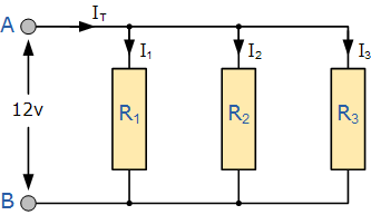
Figure3
Suppose we have three resistors in parallel, with resistances R1, R2, and R3. The equivalent resistance, denoted as RT, is given by:
1/RT = 1/R1 + 1/R2 + 1/R3
Simplifying this equation will give us the value of RT.
Remember, in this case, we are using the reciprocal values (1/R) of the resistances, not the resistances themselves. By following this approach, we can determine the equivalent resistance of a parallel resistor circuit.
3. Equation in Series vs Parallels
3.1 Series Resistor Equation
The total or equivalent resistance, RT, in a series circuit is the algebraic sum of the individual resistances. It has the same effect on the circuit as the original combination of resistors.
When two equal resistances or impedances are connected in series, the total resistance, RT, is equal to twice the value of one resistor (2R). For example, if two equal resistors are connected in series, the total resistance would be 2R. Similarly, if three equal resistors are connected in series, the total resistance would be 3R, and so on.
If two series resistors or impedances are unequal and of different values, the total resistance, RT, is equal to the mathematical sum of the two resistances (R1 + R2). The equivalent resistance of three or more unequal (or equal) resistors connected in series can be calculated by adding up all the individual resistances (R1 + R2 + R3 + ...).
It is important to note that in series networks, the total resistance (RT) of any two or more resistors connected in series is always greater than the value of the largest resistor in the chain. For example, if the largest resistor value is 6k, the total resistance (RT) would be greater than 6k. In our previous example, RT was calculated to be 9k.
3.2 Parallel Resistor Equation
In a parallel circuit, the equivalent resistance, RT, is calculated by taking the inverse of the algebraic sum of the inverses of the individual resistances.
When two parallel resistances or impedances are equal and of the same value, the total resistance, RT, is equal to half the value of one resistor (R/2). For example, if two equal resistors are connected in parallel, the total resistance would be R/2. Similarly, if three equal resistors are connected in parallel, the total resistance would be R/3, and so on.
As more parallel resistors are added, the total resistance, RT, always decreases because the equivalent resistance is always less than the smallest resistor in the parallel network. This means that adding more parallel resistors provides an easier path for current flow, resulting in a lower overall resistance.
4. Examples
4.1 Resistors in Series Example
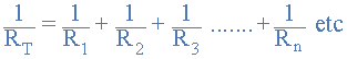
In this example, we are going to calculate the voltage drops across resistors X and Y in a series circuit. Let's analyze the circuit with and without RL (load resistor) connected.
a) Without RL connected:
In this case, the output voltage Vout is the required output voltage of 6V. The voltage drop across resistor X is also 6V, as it is the only resistor in the circuit. Similarly, the voltage drop across resistor Y is also 6V.
b) With RL connected:
When the load resistor RL is connected, the output voltage Vout drops to 4V. This is because the presence of RL affects the voltage division in the circuit. The output voltage Vout is determined by the ratio of resistors R1 and R2. As RL approaches infinity ( ), the loading effect diminishes, and the voltage ratio of Vout/Vs is unaffected by the load on the output. In other words, as the load impedance increases, the loading effect on the output decreases.
It is important to note that attenuation is the effect of lowering a signal or voltage level. When using a voltage divider network, caution must be exercised to account for the loading effect. One way to compensate for this effect is by using a potentiometer instead of fixed value resistors and adjusting it accordingly. This method also helps compensate for variations in resistor tolerances.
4.2 Resistors in Parallel
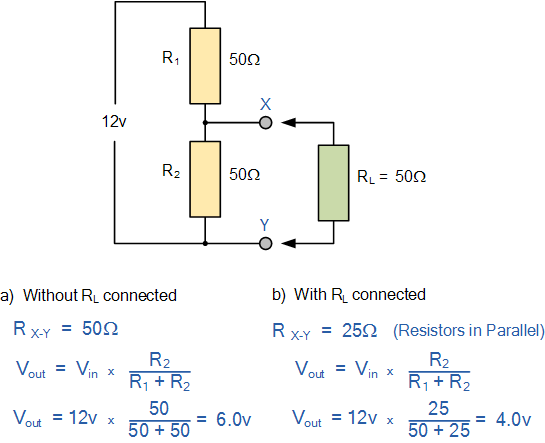
In this section, we will find the total resistance (RT) of resistors connected in a parallel network. Let's consider the circuit shown in Figure 6.
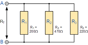
Figure 6
To calculate the total resistance RT, we can use the reciprocal calculation method. The reciprocal of the total resistance is equal to the sum of the reciprocals of the individual resistances. This method can be used for any number of resistors connected in parallel.
However, if there are only two resistors connected in parallel, we can use a simpler and faster formula to find the total or equivalent resistance value, RT. This formula helps reduce the need for reciprocal calculations.
In Figure 7, we have a single parallel network with two resistors. To find the total resistance RT, we can use the formula:

Figure 7
RT = (R1 * R2) / (R1 + R2)
This formula provides a quick way to calculate the total resistance when there are only two resistors in parallel.
By understanding these concepts and formulas, you can effectively analyze and calculate resistances in series and parallel circuits.
5. Applications
We have previously discussed how resistors in series are used to generate different voltages across themselves and how this configuration can be used to create a voltage divider network. By replacing one of the resistors in the voltage divider circuit with a sensor such as a thermistor, light-dependent resistor (LDR), or even a switch, we can convert an analog quantity being sensed into a suitable electrical signal that can be measured.
6. Summary
6.1 Resistors in Series Summary
When two or more resistors are connected end-to-end in a single branch, they are said to be connected in series. In a series circuit, the resistors carry the same current, but the voltage drop across each resistor is different due to their resistance values. This voltage drop can be calculated using Ohm's Law (V = I * R). Series circuits are often referred to as voltage dividers.
The total resistance of a series resistor network, denoted as RT, is equal to the sum of the individual resistances. Swapping the positions of the resistors in a series circuit does not affect the total resistance, current, or power to each resistor or the circuit as a whole.
6.2 Resistors in Parallel Summary
When two or more resistors are connected in such a way that their terminals are connected to the terminals of the other resistors, they are said to be connected in parallel. In a parallel combination, the voltage across each resistor is the same, but the currents flowing through them are different due to their resistance values and Ohm's Law. Parallel circuits are often used as current dividers.
To find the equivalent or total resistance, denoted as RT, of a parallel combination, reciprocal addition is used. It is important to note that the total resistance value in a parallel circuit is always less than the resistance of the smallest individual resistor in the combination. Within the same parallel combination, the positions of the resistors can be swapped without changing the total resistance or total circuit current. Additionally, even if one resistor in a parallel circuit is open-circuited, the other resistors will continue to operate.
7. FAQ
1. How do you calculate resistors in series?
In a series circuit, the total resistance can be calculated by adding up the individual resistances of each component connected in series. The formula to calculate the total resistance in a series circuit is:
RT = R1 + R2 + R3 + ...
For example, if we have resistors with values of 2 ohms, 2 ohms, and 3 ohms connected in series, the total resistance would be:
RT = 2 + 2 + 3 = 7 ohms.
Therefore, the total resistance in this series circuit is 7 ohms.
2. Do you add up resistance in series?
Yes, in a series circuit, you add up the individual resistances to find the total resistance. This is because the current has to flow through each component in series, and the total resistance is the sum of all the resistances in the circuit.
To determine if two resistors are in series or parallel, you can look at the nodes in the circuit. If the nodes at both ends of the resistors are the same, then they are in parallel. If only one node is the same, then they are in series.
3. Which resistor gets the most current?
The resistor that has the most current passing through it depends on its resistance value and the voltage applied across the circuit. According to Ohm's Law (I = V/R), the current flowing through a resistor is inversely proportional to its resistance. So, the resistor with the lowest resistance will have the most current passing through it.
For example, if we have resistors with values of 2 ohms, 3 ohms, and 5 ohms connected in series and a voltage of 10 volts applied across the circuit, we can calculate the current passing through each resistor:
I1 = 10/2 = 5 Amps
I2 = 10/3 ≈ 3.33 Amps
I3 = 10/5 = 2 Amps
Therefore, the 5-ohm resistor will have the most current passing through it, which is 5 Amps.
4. What is resistor connected in parallel?
Resistors are connected in parallel when their terminals are connected to the same two nodes in a circuit. In a parallel circuit, the equivalent overall resistance is smaller than the smallest resistance among the parallel resistors. This is because each resistor in parallel has the same full voltage applied to it, but the total current is divided among them.
For example, if we have resistors with values of 2 ohms, 3 ohms, and 5 ohms connected in parallel, the equivalent resistance would be:
1/RT = 1/R1 + 1/R2 + 1/R3 + ...
1/RT = 1/2 + 1/3 + 1/5
Solving this equation gives us the reciprocal of the total resistance:
1/RT ≈ 0.833
Therefore, the total resistance in this parallel circuit is approximately 1.2 ohms.
5. What happens to resistors in parallel?
When resistors are connected in parallel, more current flows from the source compared to when they are connected individually. This is because the total resistance in a parallel circuit is lower than the resistance of any individual resistor. Each resistor in parallel has the same full voltage applied to it, but the total current is divided among them.
For example, if we have resistors with values of 2 ohms, 3 ohms, and 5 ohms connected in parallel, the total current flowing from the source would be:
I = V/RT
Assuming a voltage of 10 volts applied across the circuit, we can calculate the total current:
I = 10/1.2 ≈ 8.33 Amps
Therefore, when resistors are connected in parallel, more current flows from the source, and the total resistance decreases.
6. Why do resistors decrease resistance in parallel?
In a parallel circuit, the net resistance decreases as more resistors are added because there are more paths for the current to pass through. Each resistor in parallel has the same potential difference (voltage) applied across it, but the total current in the circuit is the sum of the currents through each branch.
As a result, the total resistance decreases because the current can flow through multiple paths simultaneously. This is why the equivalent overall resistance in a parallel circuit is smaller than the smallest resistance among the parallel resistors.


Company
About UsContact UsTerms & ConditionsPrivacy StatementPayment,Shipping & InvoiceRefund & Return PolicyWarranty PolicyFrequently asked questionHolidays for Chinese Mid-Autumn Festival and National Day in 2023 Copyright © 2022-2024 Power by Chipdatas Trading Limited. All Rights Reserved.