Optimizing Device Cooling: Thermal Design and Heat Sink Calculations
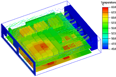
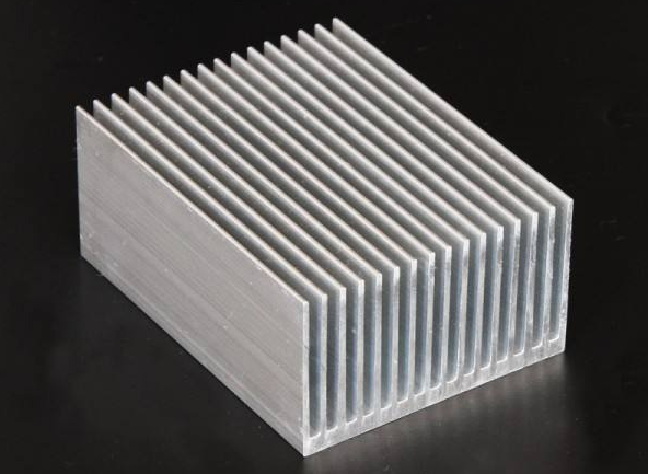
The heat sink plays a crucial role in the thermal management of electronic devices. It utilizes a thermal conductor to transfer heat away from the device and into fins, which provide a large surface area for the heat to dissipate. This process effectively cools both the heat sink and the processor. To facilitate airflow and enhance cooling efficiency, both heat sinks and radiators are equipped with built-in fans.
Currently, thermal failure is the primary cause of electronic equipment malfunctions. In fact, statistics show that 55% of electronic equipment failures can be attributed to temperature exceeding the rated value. As temperature rises, the failure rate of electronic equipment increases exponentially. Therefore, the thermal design of power devices plays a crucial role in the overall structural design of electronic equipment, as it directly impacts the success of the products. A well-executed thermal design serves as the foundation for stable and reliable equipment operation.
1. Main Parameters of Thermal Properties
The thermal stress experienced by power devices can originate from both internal and external sources. If the device has limited heat dissipation capabilities, the power consumption will cause an increase in temperature, specifically in the active region of the chip inside the device. This rise in temperature can reduce the device's reliability and prevent it from functioning safely. The key parameters used to characterize the thermal capacity of power devices are the junction temperature and thermal resistance.
The active region of the device refers to various areas such as the PN junction region of a junction device (e.g., a transistor), the channel region of a field-effect device, diffused resistors, or thin film resistances in integrated circuits.
When the junction temperature (Tj) exceeds the ambient temperature (Ta), heat is transferred through a temperature difference, resulting in a diffusive heat flow. This heat is emitted from the chip through the tube shell, and the amount of heat emitted increases with the temperature difference (Tj-Ta).
To ensure that the device can operate reliably over an extended period, a maximum allowable junction temperature (Tj max) is defined. Tj max is determined by the materials used in the chip, packaging materials, and device reliability.
The heat dissipation capability of power devices is typically characterized by thermal resistance, denoted as Rt. A higher thermal resistance indicates poorer heat dissipation ability. Thermal resistance can be further divided into internal and external thermal resistance.
Internal thermal resistance refers to the inherent thermal resistance of the device itself, which is influenced by factors such as thermal conductivity, thickness, cross-sectional area of the tube core, shell material, and processing technology. On the other hand, external thermal resistance is influenced by the form of the tube package. Generally, a larger shell area results in a smaller external thermal resistance. Metal shells typically have lower external thermal resistance compared to plastic shells.
When the power consumption reaches a certain level, the junction temperature of the device rises, leading to a decrease in system reliability. To improve reliability, it is important to carry out thermal design for power devices.
2. Thermal Design of Power Device
The thermal design of power devices is crucial in preventing thermal failure resulting from overheating or rapid temperature changes. It encompasses various aspects such as the internal chip, package, tube, and practical usage.
In the case of typical power devices, it is necessary to consider the thermal design of the interior chip, package, and tube. However, for power devices with high power consumption, it is important to install a suitable radiator. This radiator facilitates efficient heat dissipation, ensuring that the device operates within a safe junction temperature range, thereby maintaining its normal functioning and reliability.
3. Heat Dissipation Calculation
The most commonly used method for heat dissipation is to install a power device on a radiator, which disperses the heat into the surrounding environment. If necessary, a fan can be added to enhance the heat dissipation by increasing the airflow.
In some cases, a flow cold water cooling plate is used for larger power devices, as it provides better heat dissipation. Heat dissipation calculation is necessary to determine the appropriate measures and radiators needed under specific working conditions.
During the heat transfer process, there is a certain thermal resistance. The thermal resistance from the core of the device to the bottom is denoted as Rjc, the resistance between the bottom and the radiator is Rcs, and the resistance of the radiator in dispersing heat into the surroundings is Rsa. The total thermal resistance is calculated as Rja = Rjc + Rcs + Rsa.
To ensure the device operates within acceptable limits, the maximum power loss of the device (Pd) and the permitted junction temperature (Tj) are considered, along with the ambient temperature (Ta). The reasonable total thermal resistance (Rja) can be determined using the following formula: Rja ≤ (Tj - Ta) / Pd
The maximum allowable thermal resistance of the radiator (Rsa) can be calculated as: Rsa ≤ (Tj - Ta) / Pd - (Rjc + Rcs)
For design considerations, Tj is typically set to 125℃, and Ta ranges from 40℃ to 60℃, depending on the ambient temperature conditions. The size of Rjc depends on the core size and package structure, which can be found in the parameter list. The size of Rcs depends on the installation technology and device packaging. If heat conducting grease or heat transfer pads are used during installation with the radiator, the typical value of Rcs ranges from 0.1 ℃/W to 0.2 ℃/W. However, if the device's bottom surface is not insulated and additional mica insulation is required, Rcs can reach 1 ℃/W. Pd represents the maximum power loss, which is calculated based on the specific working conditions of the device. By calculating Rsa, an appropriate radiator can be selected.
4. Calculation Example
A power operational amplifier, the PA02, is used as a low-frequency power amplifier. The device comes in an 8-pin TO-3 metal shell package. The operating conditions for the amplifier are as follows: the operating voltage, Vs, is 18 V; the load impedance, RL, is 4Ω; the ambient temperature is 40 ℃; and natural cooling is employed.
According to the data provided for the PA02, the typical value of the static current, Iq, is 27mA, with a maximum value of 40mA. The typical value of the thermal resistance, Rjc (from tube core to shell), is 2.4 ℃/W, and the maximum value is 2.6 ℃/W. The power consumption of the device can be calculated as follows:
Pdq = Iq(Vs + |-Vs|)
Pdout = Vs^2 / (4RL)
Iq = 37mA
Pd = Iq(Vs + |-Vs|) + Vs^2 / (4RL)
= 0.037 × (18 + 18) + 18^2 / (4 × 4)
= 21.6 W
The thermal resistance of the radiator, Rsa, should satisfy the following condition: Rsa ≤ (Tj - Ta) / Pd - (Rjc + Rcs)
Given that Tj = 125℃, Ta = 40℃, Rjc = 2.6℃/W, and Rcs = 0.2℃/W (PA02 is installed directly on the radiator with heat conductive grease in between), substituting these values into the formula yields Rsa ≤ (125 - 40) / 21.6 - (2.6 + 0.2) ≤ 1.135℃/W
The thermal resistance of HSO4 in natural convection is 0.95 ℃/W, which meets the heat dissipation requirement.
5. Selection of Radiator
Radiators are commonly used components that can be customized to meet specific needs. They are treated with electrophoretic coating or black oxygen polarization to enhance heat dissipation and insulation performance.
The electrophoretic coating increases natural cooling efficiency by 10% to 15%, and ventilation cooling efficiency by 3%. Additionally, it can withstand pressures of 500V to 800V. Radiator manufacturers provide information on the heat resistance of different types of radiators under various heat dissipation conditions.
The primary purpose of a radiator is to regulate the temperature of power devices, particularly the junction temperature (Tj), ensuring it remains below the safe limit. This improves the reliability of the power device.
Traditional radiators are often standardized, serialized, and universal. However, new products are being developed to have low thermal resistance, multifunctionality, small volume, lightweight, and suitability for automatic production and installation.
Different power devices have varying internal thermal resistances, and variations in contact surface and installation torque can lead to differences in thermal resistance between connections.
The key factor in selecting a radiator is the heat resistance (Rtf). Power devices have different heat dissipation requirements under different environmental conditions. Therefore, when choosing an appropriate radiator, factors such as environmental conditions, compatibility with the power device, and the overall volume and quality of the electronic equipment should be considered.
To begin, calculate whether the junction temperature of the power device, based on its performance and environmental parameters during normal operation, falls within a safe range. If a radiator is necessary, calculate the corresponding thermal resistance required for the radiator.
Recalculate the junction temperature of the power device to determine if it falls within the safe range with the selected radiator. If it does, proceed with the optimal design based on the specific engineering requirements.
6. Conclusion
By analyzing and calculating the heating principle of power devices, we can provide guidance for the design of heat dissipation methods and the selection of radiators. This ensures that power devices operate within a safe temperature range, reducing the occurrence of quality issues and enhancing the reliability of electronic products.
The reliability of electronic equipment is influenced by various factors, including components, structure, assembly, processes, and processing quality. In real-world engineering applications, it is essential to gather feedback data through various tests in order to refine the design and further enhance the reliability of electronic equipment.
7. FAQ
1. What is a heat sink and how does it work?
A heat sink, also spelled as heatsink, is a passive heat exchanger that effectively transfers the heat generated by an electronic or mechanical device to a fluid medium, such as air or liquid coolant. By dissipating the heat away from the device, the heat sink helps regulate the temperature of the device and prevent overheating.
2. What is a heat sink used for?
A heat sink is primarily used to enhance the heat dissipation from a hot device. It achieves this by increasing the device's surface area and facilitating the movement of low-temperature fluid across the enlarged surface area.
3. Does a heat sink need a fan?
In most cases, heat sinks have denser fins that require the use of a fan directly mounted on the heat sink. If a heat sink incorporates heat pipes (copper tubes running through the fins), it is usually designed to be used with a fan. However, it is possible to test whether a heat sink can safely operate without a fan.
4. What material dissipates heat the best?
Thermal conductivity is the measure of a metal's ability to conduct heat. Metals with high thermal conductivity, such as copper and aluminum, are effective at dissipating heat. On the other hand, metals like steel and bronze have lower thermal conductivity and are less efficient at dissipating heat.
5. How many types of heat sinks are there?
Heat sinks can be categorized into two main types: active and passive heat sinks.
6. What is the difference between active and passive heat sinks?
An active heat sink is equipped with a fan that actively pulls heat away from the heat sink and the underlying chip. In contrast, a passive heat sink consists of a flat metal piece with fins that passively direct heat away from the chip set it is installed on.
7. Which is better, a heat sink or a fan?
Generally, when combined with good airflow provided by a fan, heat sinks can be smaller in size. However, the only advantage of using a heat sink alone is reduced noise. It is preferable for the heat sink fins to be oriented upwards so that hot air can rise off the heat sink while cool air is pulled in.
8. What is the difference between a heat sink and a CPU fan?
A heat sink is responsible for drawing heat away from the CPU, while a fan ensures a continuous stream of air to facilitate the transfer of heat from the heat sink. Selecting a suitable heat sink and fan involves considering factors beyond price or appearance.
9. What is the difference between a heat sink and a heat pipe?
Heat pipes are typically used to spread heat to a nearby heat sink, while vapor chambers are more effective at transferring heat to a remote heat sink. If a heat sink needs to cover an area that is at least 10 times, and usually closer to 20 times, the size of the heat source, vapor chambers are recommended.
10. How is a heat sink attached to an electrical component?
A heat sink is a mechanical component that is attached to an electrical component to facilitate the transfer of heat from the electrical component to the surrounding environment. This is typically achieved by using air as the medium, but other fluids like water or coolant can also be used.


Company
About UsContact UsTerms & ConditionsPrivacy StatementPayment,Shipping & InvoiceRefund & Return PolicyWarranty PolicyFrequently asked questionHolidays for Chinese Mid-Autumn Festival and National Day in 2023 Copyright © 2022-2024 Power by Chipdatas Trading Limited. All Rights Reserved.