Master the principle of DC-DC step-up, easily understand the case + pictures and texts
1. What is a DC-DC Converter?
DC-DC converters are a type of power electronic circuit that can convert DC voltage from one level to another, and are an essential component in modern electronic products. Compared to linear regulators, DC-DC converters have many advantages, with the most important being their high efficiency. Linear regulators dissipate a lot of heat, but the switching regulator in a DC-DC converter can avoid this situation, making it very efficient.
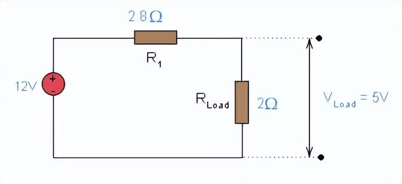
To better understand the working principle of DC-DC converters, we can use an example to illustrate their use. Suppose we need to build a circuit with a load resistance of 2Ω, a DC power supply voltage of 12V, and a load voltage of 5V. To reduce the voltage of the 12V battery and provide a 5V voltage to the load, we can connect a 2.8Ω resistor in series with the load. However, this method wastes a lot of energy because the load only consumes 12.5W of input power, and the rest (30 - 12.5 = 17.5W) is converted into heat. To get a better solution, we can use a DC-DC converter.
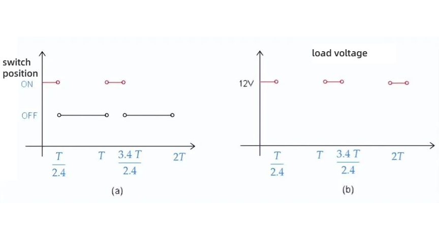
The switching regulator in a DC-DC converter can change the input voltage by controlling the position of the switch. When the switch is open, the input voltage is 0V; when the control is in the ON position, the input voltage is 12V. We can use the switch control method shown in Figure (a) to obtain the voltage waveform shown in Figure (b). In this case, the average output voltage of the switch behavior is 5V.
However, finding an ideal switch in practical applications is difficult, so there will be some power loss in reality. But even with power loss, DC-DC converters still have high efficiency. If we assume that the switch is ideal, that is, it does not consume or dissipate power from the power source, we can calculate the efficiency of the circuit as 100%. When the switch is in the ON position, the current flowing through the circuit is 6A. Since we have an ideal switch, the dissipated power is P_diss = RI 2 = 0 * 9 2 = 0W. When the switch is in the closed position, no current flows through the switch, so the dissipated power is also 0 in this case.
To improve the output waveform, we can use an RC filter circuit to remove harmonics. Although there may be power loss in practical applications, DC-DC converters still have high efficiency, making them an indispensable part of modern electronic products.
2. DC-DC boost circuit
DC-DC boost circuit is mainly used to increase the voltage of the power supply, such as boosting a 5V power supply to 25V. This circuit is usually used in battery chargers or solar panels, and can also be used to power components with different operating voltages.
A general schematic of a boost converter:
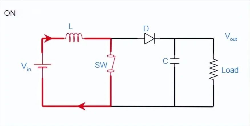
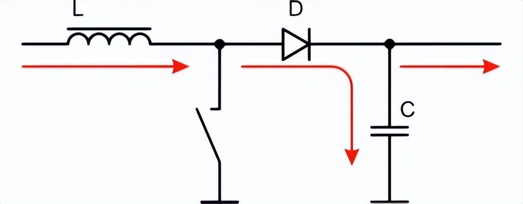
1. The boost switch is on
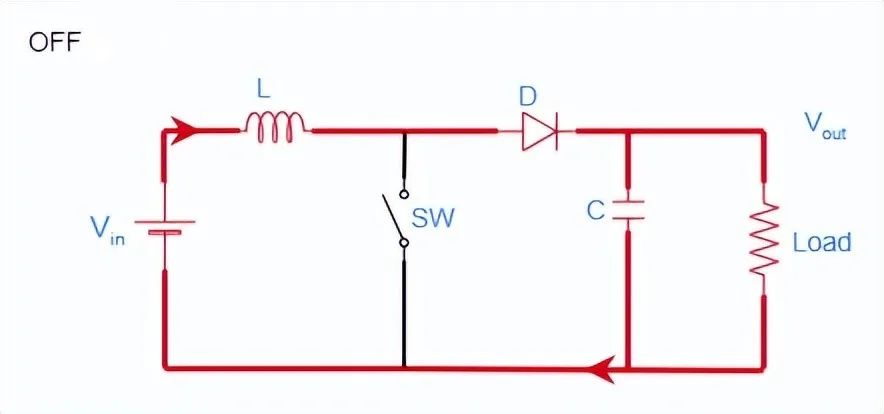
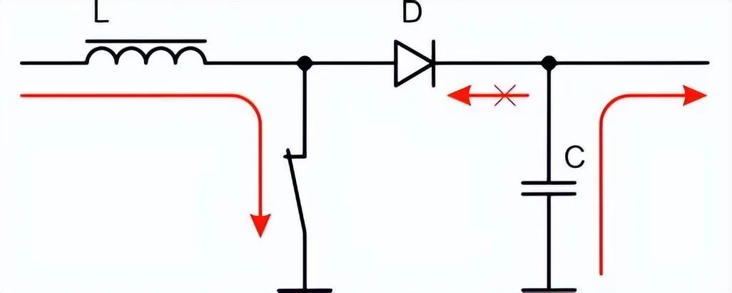
2. The boost switch is off
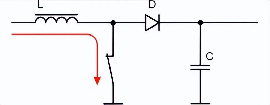
The general schematic diagram of the boost converter includes a DC power supply (Vin), inductor (L), diode (D), switching device (SW), smoothing capacitor (C), and load resistor (Load), with the output voltage being Vout.
The switch is usually a power electronic device, such as a MOSFET or BJT transistor controlled by a PWM signal. The PWM signal works by rapidly switching the transistor, typically thousands of times per second.
3. Working principle of DC-DC boost circuit
Assuming the voltage in the current circuit is 5V, if we need to increase the voltage, we can use a DC-DC boost circuit to achieve this. Below, we will explain this process from the perspective of a pipeline worker.
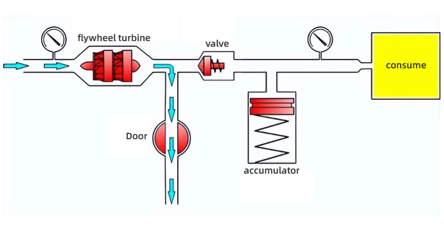
1. Accelerate the turbine
First, we need to accelerate the turbine. To do this, we open the throttle and let the water flow quickly, transferring some of the energy to the turbine, thereby causing the turbine to start rotating.
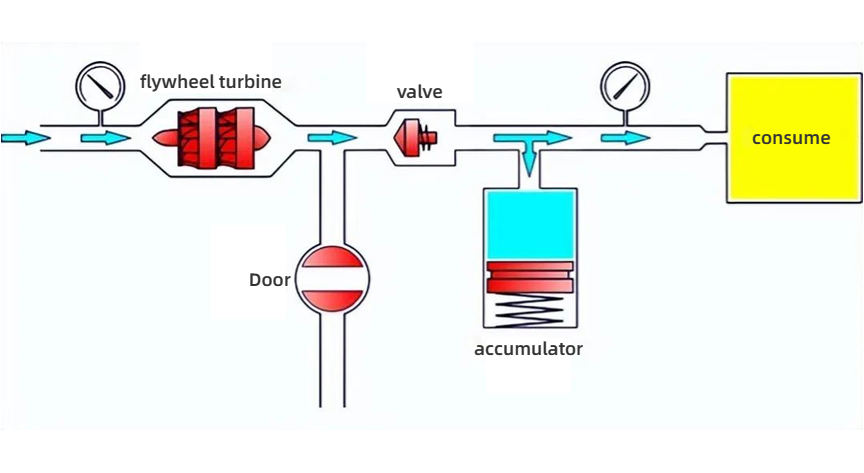
2. Fill the pressure tank
Next, we close the throttle, and the rotation of the turbine drives the water flow through the valve, filling a part of the water into the storage tank, while the other part of the water flows to the consumer under the high pressure provided by the storage tank. The valve can also prevent water from flowing back.
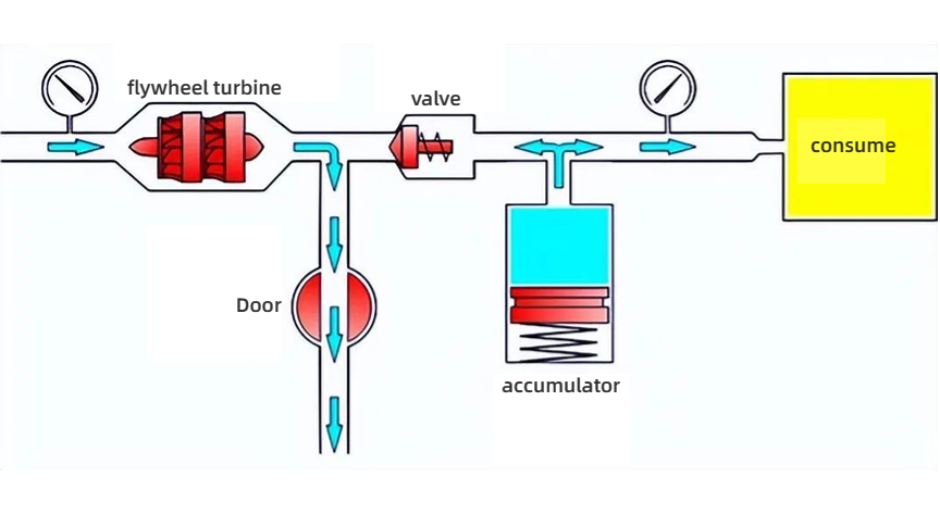
3. Generate electricity and accelerate the turbine
When the speed of the turbine begins to decrease, the water can no longer push the valve, but there is still enough energy accumulated in the storage tank. Then we open the throttle again, and the water quickly rotates the turbine. Since the consumer receives energy from the storage tank, the energy flowing to the consumer will not stop, and then the cycle repeats.
Now, we will switch from pipeline equipment to electronic equipment. We use an inductive throttle valve instead of a turbine, and a transistor instead of a throttle valve that controls water flow. The diode acts as a valve, and electricity replaces the pressure tank.
Now we can understand the working principle of the DC-DC boost circuit.
1. Inductance accumulates charge
When the switch is closed, the inductor accumulates energy by receiving current from the source.
2. Transfer energy to the capacitor
When the switch is opened, the coil maintains the energy accumulated in the magnetic field. The current tries to remain at the same level, but the additional energy from the inductor increases the voltage, thereby opening the path through the diode. Part of the energy flows to the consumer, while the remaining energy accumulates in the capacitor.
3. Accumulate energy in the inductor and transfer charge to the consuming circuit
Then, we lock the switch, and the coil starts to accumulate energy again, while the consuming circuit receives energy from the capacitor.
4. How to Build a DC-DC Boost Circuit
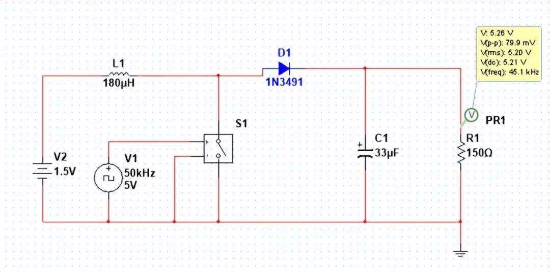
Building a DC-DC Boost Converter from 1.5V to 5V
1. To build a DC-DC boost converter, we need the following components:
- A 1.5V DC power supply
- A 180uH inductor
- A 1N3491 diode
- A 33uF capacitor
- A 150 Ω resistor
- A MOSFET or JFET switching transistor
- A PWM source, such as an Arduino Uno or 555 timer, which can generate a 50KHz, 5V, 75% duty cycle.
2. The working principle diagram of the DC-DC boost converter is shown below:
This concludes the introduction to the DC-DC boost converter.


Company
About UsContact UsTerms & ConditionsPrivacy StatementPayment,Shipping & InvoiceRefund & Return PolicyWarranty PolicyFrequently asked questionHolidays for Chinese Mid-Autumn Festival and National Day in 2023 Copyright © 2022-2024 Power by Chipdatas Trading Limited. All Rights Reserved.