- Deliver to
 USLanguageEnglish


Enter the order reference number received by email to check the status or make payment.
 Purchase Protection
Powerful Protection from Payment to Delivery
Secure and Reliable Payment
Money Back Guarantee
Shipping and Delivery
After-Sales Service
MCU (Micro Controller Unit): An integrated circuit chip for intelligent control
This article aims to provide a comprehensive introduction to the MCU (Microcontroller Unit), delving into its internal structure analysis and explaining important concepts. One particular focus will be placed on the concept of memory decoding.
2 What is an MCU?
An MCU (Microcontroller Unit) is an integrated circuit chip that combines various components to form a complete computer system. It incorporates a microprocessor (CPU) with data-handling capabilities such as arithmetic, logic operations, and data transfer. Additionally, it includes random access data memory (RAM), read-only program memory (ROM), input and output circuits (I/O ports), timing counters, serial communication ports (SCI), display drive circuits (LCD or LED drive circuits), pulse width modulation circuits (PWM), analog multiplexers, and A/D converters.
These integrated circuits, under the control of software, enable accurate, fast, and efficient execution of tasks as specified by the program designer. In this sense, the MCU possesses functions that go beyond those of a standalone microprocessor, providing intelligent control capabilities that are increasingly demanded in modern industrial applications. This is the most notable characteristic of an MCU.
2 Some Basic Concepts
2.1 The Meaning of ROM
Let's consider a scenario: when we write instructions into an MCU using a programmer and then remove it, the MCU can still execute the instructions. This means that the instructions must be stored somewhere in the MCU, and this storage location should retain the instructions even after power-off. Where is this place? It is the internal ROM of the MCU, which stands for read-only memory. Why is it called read-only memory? We use a programmer, an external device, to write data to the ROM under specific conditions. During normal operation of the MCU, the data in the ROM can only be read and cannot be written, hence the name ROM.
2.2 The Meaning of Bit
From the previous experiment, we have learned that the state of a lamp or a line can represent two states: 0 and 1. This binary state is referred to as a bit, and it is expressed as BIT.
2.3 The Meaning of Bytes
A single line can represent the states 0 and 1. Two lines can express four states: 00, 01, 10, and 11, which correspond to the values 0 to 3. Similarly, three lines can express eight states, representing the values 0 to 7. In computers, eight lines are typically grouped together, and when counted simultaneously, they can represent the values 0 to 255, encompassing a total of 256 states. This group of eight lines, or 8 bits, is called a byte (BYTE).
3 The Working Principle of Memory
Structure
The instructional systems of a single-chip microcomputer are responsible for executing all the instructions it can perform. Different types of single-chip computers have different instructional systems. In order for a single-chip microcomputer to automatically complete a specific task, the problems that need to be solved must be programmed into a series of instructions that can be recognized and executed by the selected single-chip microcomputer. These instructions are integrated into a program, which needs to be stored in memory, a storage unit.
Memory is composed of multiple storage units, similar to how a building has many rooms, with each room assigned a unique room number. Similarly, each storage unit is assigned a unique address number, known as the address of the storage unit, so that the address of the storage cell can be identified. The instructions are stored in these units, and the storage unit can be accessed to retrieve the stored instructions for execution.
SCM Sample
Memory serves as the storage place for data. It uses different electric voltage levels to represent and store data. Instead of storing numbers like 1234, memory actually stores the electrical levels. You can think of memory as a series of small drawers, where each drawer represents a "bit" of data. These bits are stored as charges that can be either present or absent, and the charges are manipulated through the wires connected to the drawers. You can visualize the wires as pipes and the charges in the grid as water, making it easier to understand.
With this structure, we can begin storing data. For example, if we want to store the data 12, which is represented as 00001100 in binary, we simply need to fill the second and third drawers with charges while leaving the other drawers empty. However, a problem arises when dealing with a large number of memory cells. Since the lines are parallel, when you put a charge into one cell, it affects all the other cells as well. Similarly, when you release a charge, it is released from every cell. This means that regardless of the number of cells in the memory, they all receive the same charge, which is not the desired outcome.
To address this issue, a slight structural change is made. Each storage unit is equipped with a control line, and to store data in a specific unit, a signal is sent to the control line of that unit. This activates the switch, allowing the charge to flow freely. On the other hand, the control lines of other units do not receive a signal, so their switches remain off and are not affected. By manipulating the control lines of different units, it becomes possible to write different data to each unit. Similarly, to retrieve data from a specific unit, the corresponding control switch is turned on.
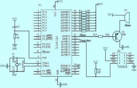
4 MCU Circuit
A circuit is composed of components connected by wires. In analog circuits, wiring is usually straightforward due to the serial relationship between devices and the limited number of connections. However, computer circuits, especially those incorporating microcontrollers (MCUs), are different. The microprocessor serves as the core, and every device must be connected to it in order to coordinate their operations. Consequently, a large number of connections are required.
If we were to approach MCU circuits in the same way as analog circuits, the number of lines between microprocessors and devices would be staggering. To address this issue, the concept of a bus has been introduced to microprocessors, allowing multiple devices to share connections. All eight data lines are connected to eight common lines, effectively creating a parallel connection for each device. However, this alone is insufficient. In a scenario where two devices simultaneously transmit data, with one sending a 0 and the other sending a 1, it would be unclear what the receiver would actually receive. To prevent such conflicts, control lines are utilized to enable time-sharing among devices. This ensures that only one device can send data at any given time (though multiple devices can receive data simultaneously).
5 Memory Decoding
Memory decoding is a crucial aspect of controlling the control lines of each unit in an integrated circuit. In the case of a model 27512 memory, which consists of 65,536 units, it is impractical to lead out each control line individually due to the enormous number of required connections. To address this issue, a technique called decoding is employed.
Decoding involves using a smaller number of lines to represent a larger number of states. For example, one line can represent two states, two lines can represent four states, and three lines can represent eight states, and so on. By implementing decoding, it is possible to reduce the number of required lines to just 16, while still being able to represent 65,536 states.
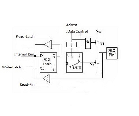
Once the decoding problem is solved, another challenge arises: how to connect the eight lines in each unit to the computer and other devices. It is not ideal for a unit to be constantly connected to all eight lines since these lines are not solely dedicated to memory operations. For instance, if the value in a memory cell is 0FFH, but the unit connected to it is OOH, it becomes unclear whether the line should be set at a high level or a low level.
To address this issue, a solution is implemented. Instead of directly connecting the outside wires to the units, a set of switches is added in between. These switches are normally left off, but they can be turned on when data needs to be written to or read from the memory. The selection of these switches is controlled by three leads: read control, write control, and chip selector.
To write data into the memory chip, the chip needs to be selected first, followed by sending a write signal. This turns on the switch, allowing the incoming data to be written into the memory chip. On the other hand, to read data from the memory chip, the chip needs to be selected first, followed by sending a read signal. This turns on the switch, enabling the data to be sent out. It's important to note that the read and write signals are also connected to another memory simultaneously, but the chip selector ends are different. This ensures that there are no conflicts or misunderstandings between the two memories.
In a properly designed system, it is not possible to select two chips simultaneously. The system is controlled by a computer, not by a human, and any occurrence of selecting two chips at the same time would indicate a circuit malfunction.
MCU Sample
As mentioned earlier, the eight lines used for data transmission are not dedicated solely to memory operations but are shared by multiple devices. This collection of data lines is referred to as the data bus. Similarly, the control lines of the device are known as the control bus. A single chip contains memory cells in both internal and external memory, as well as other devices. Before these units can be utilized, they must be assigned addresses, which are represented as electrical signals. Due to the large number of memory cells, numerous lines are required for address allocation, and these lines are called address buses. In this case, there are sixteen address lines connected, forming the address buses.
6 FAQ
1. What are the characteristics of a microcomputer?
a. Small size and low cost.
b. Designed for one user.
c. Easy to use.
d. Lower computing power compared to other computers.
e. Commonly used for personal applications.
2. What are the advantages of a microcomputer?
a. Widely used in various applications today.
b. Small in size.
c. Used for designing different software and apps.
d. Affordable cost, making it accessible to all users.
e. Doesn't require highly trained staff for operation.
3. Why are microcontrollers often called single-chip computers?
Microcontrollers, such as the PIC range by Microchip Inc, are commonly used in embedded devices. They are referred to as single-chip computers because they integrate basic functionality and don't require external chips to function.
4. What is a single-chip microcomputer with everything inbuilt?
A single-chip microcomputer refers to a microcomputer built using separate components like the CPU and memory. In some cases, there are also single-chip computers available in a VLSI chip, which include a CPU, memory, I/O interfaces, timers, ADC/DACs, all on a single chip.
5. What is the difference between a microprocessor and a microcomputer?
The main difference is that a microprocessor is a computer processor contained on an integrated-circuit chip, while a microcomputer is a small, relatively inexpensive computer. Microprocessors contain both combinational logic and sequential digital logic.
6. Is Raspberry Pi a microcomputer?
Yes, the Raspberry Pi is a microcomputer often used by hobbyists to create projects such as animated LED displays or bird watchers.
7. What is a feature of a single-chip microcomputer?
A single-chip microcomputer is a major branch of microcomputers. Its biggest feature is that the CPU, memory, timer, and various input/output interface circuits are integrated on a very large-scale integrated circuit chip. In terms of composition and function, a single chip functions as a computer.
8. What are the components of a microcomputer?
The main components are:
a. The central processing unit (CPU).
b. Input devices.
c. Output devices.
d. Memory.
The CPU performs all the arithmetic, logic, and data handling functions of the microcomputer.
9. Is a microcontroller a microcomputer?
A microcontroller is a small and low-cost microcomputer designed to perform specific tasks in embedded systems, such as displaying microwave information or receiving remote signals.
10. What is the definition of a microcomputer?
A microcomputer is an electronic device with a microprocessor as its central processing unit (CPU). It was formerly a commonly used term for personal computers, particularly small digital computers with a CPU contained on a single integrated semiconductor chip.


Company
About UsContact UsTerms & ConditionsPrivacy StatementPayment,Shipping & InvoiceRefund & Return PolicyWarranty PolicyFrequently asked questionHolidays for Chinese Mid-Autumn Festival and National Day in 2023 Copyright © 2022-2024 Power by Chipdatas Trading Limited. All Rights Reserved.