Enter the order reference number received by email to check the status or make payment.
Powerful Protection from Payment to Delivery
Secure and Reliable Payment
Money Back Guarantee
Shipping and Delivery
After-Sales Service
LM386 audio power amplifier: detailed explanation of pager circuit and voice circuit
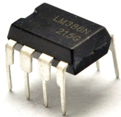
LM386 is an audio power amplifier manufactured by National Semiconductor Corporation in the United States, mainly used in low-voltage consumer products. In order to minimize peripheral components, the voltage gain is built-in at 20. Similar to general-purpose integrated operational amplifiers, it is a three-stage amplification circuit. This article will introduce the pager circuit and voice circuit composed of LM386.
1 Pager Circuit
This circuit consists of a preamplifier stage and the LM386 low-power integrated circuit. It is a simple circuit with low cost, small size, and convenient use, suitable for electronic hobbyist beginners. It has been proven to produce clear sound and can operate normally within a range of 800 meters.

Figure 1: Pager circuit schematic
The circuit principle of this pager is shown in Figure 1. When used as an intercom, the "conversation" and "speaking" functions are switched by switch K1. When switch K1 is set to "speaking," the base of the preamplifier stage 3DG12 is connected to the electret microphone. At the same time, pin 5 of LM386 is connected to the external speaker Y2 through K1. The speech input from the electret microphone is amplified by the preamplifier, power amplifier, and switched by K1 and K2, and then output through speaker Y2. The external speaker Y2 is the extension unit, and the number of speakers can be set according to needs, controlled by the internal switch K2 of the main unit. When "K1" is set to "conversation," the base of 3DG12 is connected to the external speaker Y2 through K1, and pin 5 of LM386 is connected to the internal speaker Y1 of the main unit. At this time, you can listen to the other party's conversation through Y1. If it is only used as a pager, the main unit may not be equipped with speakers and switching K1K2, making the circuit even simpler.
The components used in the pager have no special requirements, and the transistor can also be replaced with 3DG6. Speakers Y1 and Y2 can be chosen as 16-22Ω products, with a diameter of 77mm for Y2. Resistors can be 1/16W metal or carbon film resistors. Diode D is used to prevent reverse polarity of the power supply and protect internal components. During installation, except for Y1Y2, K1K2, electret microphone M, potentiometer W, and extension indicator light, which are installed in appropriate positions inside the housing, the remaining components are installed on a printed circuit board. The device can be powered by a 4.5-6V power supply. If the internal resistance of the power supply battery is too high, it may produce a "beep" sound, in which case a new battery should be replaced.
2 Voice Circuit
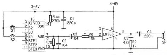
Figure 2: Circuit schematic with LM386 power amplifier
Figure 2 shows the circuit schematic with the LM386 power amplifier. The resistance value of the trim potentiometer VR in the diagram is 10kΩ. It is used to adjust the output volume. The LM386 has an output power of 500mW to 800mW. R2, C3 form a high-pass filter circuit to improve sound quality. C4 is a 220µF electrolytic capacitor.
Recent Posts




Company
About UsContact UsTerms & ConditionsPrivacy StatementPayment,Shipping & InvoiceRefund & Return PolicyWarranty PolicyFrequently asked questionHolidays for Chinese Mid-Autumn Festival and National Day in 2023
 US
US


