Enter the order reference number received by email to check the status or make payment.
Powerful Protection from Payment to Delivery
Secure and Reliable Payment
Money Back Guarantee
Shipping and Delivery
After-Sales Service
Introduction to the classic application circuit of LM386 audio power amplifier
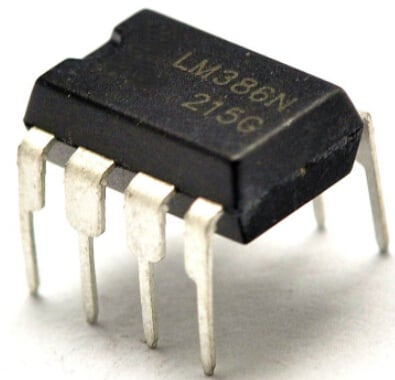
The LM386 is an audio power amplifier produced by the National Semiconductor Corporation in the United States, mainly used in low voltage consumer products. In order to minimize peripheral components, the voltage gain is internally set to 20. However, by adding an external resistor and capacitor between pin 1 and pin 8, the voltage gain can be adjusted to any value up to 200. The input terminal is referenced to ground, and the output terminal is automatically biased to half of the power supply voltage. With a 6V power supply voltage, its static power consumption is only 24mW, making the LM386 particularly suitable for battery-powered applications. Below are its application circuits:
1. Amplifier with a gain of 20
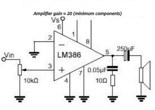
Figure 1: Circuit diagram for amplifier with a gain of 20
The application circuit in Figure 1 represents a gain of 20. Adding a 10μF capacitor between pin 1 and pin 8 will increase the gain to 200.
2. Amplifier with a gain of 200
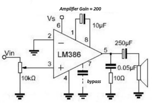
Figure 2: Circuit diagram for amplifier with a gain of 200
As shown in Figure 2, the 10k-ohm variable resistor is used to adjust the speaker volume. If Vin is directly inputted, it will be in the maximum volume state.
3. Voltage amplifier with a gain of 20
Voltage amplifier circuit with a gain of 20:
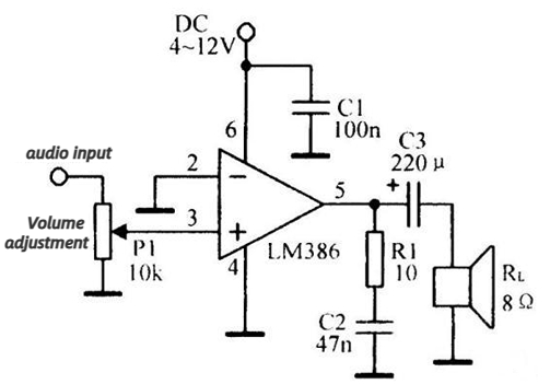
Figure 3: Circuit diagram for voltage amplifier with a gain of 20
4. Voltage amplifier with a gain of 50
Voltage amplifier circuit with a gain of 50:
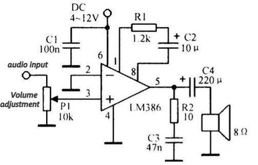
Figure 4: Circuit diagram for voltage amplifier with a gain of 50
5. Voltage amplifier with a gain of 200
Voltage amplifier circuit with a gain of 200: Amplifier circuit with 6dB gain at 85Hz:
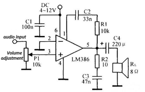
Figure 6: Amplifier circuit with 6dB gain
6. Radio power amplifier
LM386 used in radios: Amplitude modulation radio power amplifier
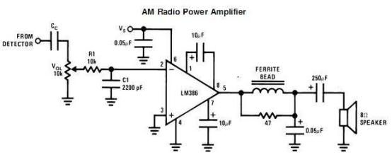
Figure 6: Circuit diagram for amplitude modulation radio power amplifier
7. Battery-powered circuit
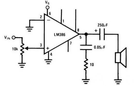
Figure 7: Battery-powered design
For example, adding a decoupling capacitor on the power line, for battery-powered designs, a 0.05mF capacitor should be sufficient. However, for other designs or if the power line is too long, it is better to parallel a 100mF electrolytic capacitor with a 0.05-0.1mF ceramic capacitor. Some people also prefer to connect a bypass capacitor to pin 7, although it is not necessary.
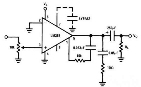
Figure 8: Circuit connection for bass enhancement
In addition, there is a circuit connection called "bass enhancement," which is similar to the function on cassette recorders in the past. However, its principle is to add a low-pass filter at the output terminal to filter out the high-frequency part. This makes it sound like the mid-frequency and low-frequency signals have been enhanced. In some electric toys, this circuit can make the sound clearer.
These are the typical application circuits of the LM386. Although the LM386 is no longer a very popular chip, it is still widely used in the DIY field as an audio amplifier chip. It is like a hammer or pliers, not something we notice every day, but once we need it, it is always reliable.
Recent Posts




Company
About UsContact UsTerms & ConditionsPrivacy StatementPayment,Shipping & InvoiceRefund & Return PolicyWarranty PolicyFrequently asked questionHolidays for Chinese Mid-Autumn Festival and National Day in 2023
 US
US


