- Deliver to
 USLanguageEnglish


Enter the order reference number received by email to check the status or make payment.
 Purchase Protection
Powerful Protection from Payment to Delivery
Secure and Reliable Payment
Money Back Guarantee
Shipping and Delivery
After-Sales Service
Example Diode Design for Enhanced Current Monitoring
The diode and the negative terminal of the power supply are connected in series to enable current monitoring. A fixed range digital multimeter (DMM) is used to measure the current. This simple design example allows for current monitoring ranging from a few microamps (μA) to 100 milliamps (mA) within a single range. This design has proven to be both effective and straightforward, requiring only 3 to 4 modules to monitor the current across the specified range.
In the Home Energy Monitor Project, the focus is on monitoring current. According to the diode formula IF≅I0 × exp (eVF/kT), the voltage across the diode increases logarithmically with the current flowing through it. In this formula, IF represents the forward current, IO is the reverse saturation current, e is the charge of an electron (1.602 × 10^(-19) C), VF is the forward voltage, T is the temperature in Kelvin, and k is the Boltzmann constant (1.380 × 10^(-23) J/K).
Depending on the specific application, the following relationship can be derived: VF∝logIF (with temperature held constant).
1 Shunt Diode
Let's discuss a design example that involves using a diode and a measuring instrument to monitor current. In this setup, when the current is low, the measuring instrument indicates the milliampere (mA) level current that flows through the meter rather than the diode. On the other hand, when the current is high, the instrument displays the voltage across the diode and calculates the logarithm of the current (assuming the diode acts as a self-adjusting shunt). As a result, the bottom of the meter scale exhibits a linear response, the top demonstrates logarithmic properties, and the middle represents a transition phase. This design provides a very useful range of current monitoring.
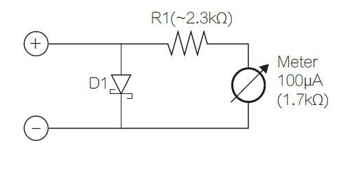
Figure 1
Figure 1 illustrates the use of a Schottky rectifier, a 100μA/1.7kΩ meter, and an appropriate series resistor to monitor current ranging from 10μA to over 100mA within a single range. The speed at which the meter indicates the current is limited by the pendulum speed of the meter.
This simple circuit, despite its minimal component count, often encounters several issues. In addition to requiring high-precision calibration, the circuit has two main drawbacks: series voltage drop and temperature stability. The diode voltage drop can be as high as 400mV, which means it is advisable to use a new or fully charged battery when performing measurements. Otherwise, the measured components may falsely indicate a low battery. Alternatively, you can consider this circuit as a convenient low-voltage test circuit and incorporate a short-circuit switch.
2 Adding an Additional Diode
At the bottom of the scale, almost all of the current flows through the meter, which is limited by the machine and magnetic temperature coefficients, with a very low measurement temperature coefficient. However, at high currents, a voltage drop across the diode can be observed, which decreases at a rate of approximately 2mV/K according to the diode equation. This not only affects the slope of the logarithmic curve but also the transition point from linear to logarithmic. Additionally, the instrument winding accounts for a significant portion of the total series resistance, and copper has a temperature coefficient of 3930 ppm/kg at room temperature. Figure 2 shows the deviation and current relationship curve of the 1N5817 at 0℃, 25℃, and 50℃. These curves take into account the temperature coefficients of the measurement circuit and the diode but ignore the self-heating effect of the latter, which is not a problem at relatively stable temperatures.

Figure 2
Self-heating primarily exists in D1 and does not affect the current. Assuming a current of 100mA flowing through D1 and a voltage drop of 400mV, this is equivalent to 40mW. According to the datasheet, the basic thermal resistance of the D0-41 1N5815 with slightly longer pins and a large amount of heat-dissipating copper is 50 K/W. When considering these data, the temperature rise at the node is only 2℃, which corresponds to a decrease in VF of approximately 4mV or an error of about 1% at full scale. It is advisable to keep the diode pins short and have high thermal mass, and be aware that there may be high transient currents during conduction, as these currents can cause errors until the node temperature cools again.
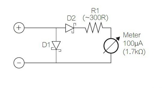
Figure 3 Improved Offset Temperature Coefficient Version

Figure 4 Offset and current curves after adding the diode
Figure 4 shows the curves of the circuit. Note that now most of the curves are in logarithmic form, and the additional diode effectively suppresses the initial linear region. However, the selection of this diode is crucial, as the forward voltage of D2 should be slightly lower than D1, but other characteristics should match.
3 LTspice
In this section, we will discuss the use of LTspice to model the circuit components. The first pair of components that we will emulate are D1 using the 10MQ060N diode and D2 using the BAT54 diode. These diodes are inexpensive and can be easily modeled in LTspice, making them recommended components for this design. It is important to note that while a pair of 10MQ060N diodes work consistently, a pair of BAT54 diodes may be inconsistent. Therefore, it is advisable to model the circuit before actually building it to account for any temperature variations and strange indications that may occur when these components are combined with others.
Silicon P-N junction diodes typically exhibit a very straight (log IF) / VF relation, whereas Schottky diodes do not. This is due to the higher series resistance and more linear behavior at very low currents in the structure of Schottky diodes. Additionally, Schottky diodes have protection loops to control the potential gradient of P-N diodes that are parallel to Schottky nodes. As a result, the exact logarithmic law will vary depending on the current and the type of diode being used.
While a used diode may suffice for the first pair of components, it is important to carefully select the double diode design due to the inherent inaccuracies in the circuit. Schottky diodes can provide more reliable reference resources in this regard.
For the 100 μA / 1700 Ω indicators, it is recommended to use components that are tightly connected and consistent in terms of linearity and structure. These indicators are commonly available and their dimensions (35mm × 14mm aperture) make them suitable for this design.

Figure 5
The calibration points shown in Figure 5 are generated by arranging various combinations of monitors, batteries, fixed and variable resistors, and a DMM (Digital Multimeter) series. The test scales are marked at the appropriate points and then removed and scanned to serve as templates for the final layout.
The simulation results are used to generate the reference points shown in Fig.5 (left), and these results accurately reflect the actual operation of the circuit, despite any limitations of the multimeter used. While these scales can save time, it should be noted that they may not be as accurate as newly made ones (since different measuring structures may require different scales). Additionally, R1 can be calibrated slightly (within ±20% of the instrument's range) to account for any non-linearity in the instrument's structure.
4 Conclusion
the circuits discussed in this article have proven to be highly effective in identifying a wide range of faults and problems, including power line short-circuits and miscoding issues in pull-up pins. As a result, these circuits have become an integral part of my development projects and production testing devices.
To ensure accurate current monitoring, it is essential to incorporate the appropriate diode and monitor its forward voltage drop. By performing a simple calibration process, it becomes possible to closely monitor the supply current in perfect synchronization with other desired parameters.
The addition of the diode allows for precise monitoring of current, enabling the detection of potential issues and deviations. This level of monitoring is crucial for maintaining the integrity and performance of various electronic systems.
Furthermore, it is important to emphasize the significance of selecting the right diode for this purpose. The diode should be chosen based on its forward voltage drop characteristics and other relevant specifications to ensure optimal performance. Careful consideration should be given to matching the diode's characteristics with the requirements of the specific application.
In addition to the diode selection, utilizing simulation tools such as LTspice can greatly aid in the design and evaluation of these circuits. Simulations can help validate the circuit's functionality and performance before implementation, saving time and resources.
Lastly, the calibration process plays a vital role in achieving accurate current monitoring. Selecting appropriate calibration points and ensuring their accuracy is essential for generating reliable reference scales. This step allows for precise interpretation and analysis of the monitored current values.
5 FAQ
1. What is a shunt diode?
A shunt diode is an electronic device that creates a low-resistance path for electric current, allowing it to bypass a specific point in a circuit. The term "shunt" originates from the verb "to shunt," which means to divert or follow a different path.
2. What is a shunt and what are its uses?
A shunt is a device that provides a low-resistance pathway for electric current to flow around a specific point in a circuit. It is commonly used as a current shunt resistor or an ammeter shunt to accurately measure the current flowing through a circuit.
3. How does a shunt diode work?
A shunt diode operates as a shunt regulator by maintaining a constant voltage across its terminals. It diverts excess current to maintain the voltage across the load. A common example of a shunt regulator is a circuit that uses a Zener diode as the shunt element.
4. What are the disadvantages of shunts?
a. Poor efficiency for large load currents.
b. High output impedance.
c. Output DC voltage is not completely constant due to the decrease in both VBB and VZ voltages with an increase in room temperature.
5. Where are shunts used?
Shunts are commonly used in galvanometers to measure large currents. They are connected in parallel to the galvanometer circuit, which serves as a current sensing device. The flow direction of current inside the circuit is determined by the galvanometer's pointer.
6. Why is a shunt always connected in parallel?
A shunt resistor is connected in parallel to a galvanometer to keep its resistance low. This allows for the use of a low-resistance galvanometer (ammeter) in series with the circuit to accurately measure the current strength.
7. How is shunt current calculated?
To calculate the shunt current:
a. Use the Ohm's law expression "V = I * R," where "V" is the voltage drop across the shunt resistor, "I" is the current flowing through the shunt, and "R" is the shunt resistance.
b. Substitute the values of voltage "V" and current "I" into the Ohm's law expression.
8. What size shunt do I need for a battery monitor?
For devices operating at 12V, such as water pumps, furnace blowers, and lights, a 100 amp shunt would be sufficient. If you have an inverter and occasionally pass up to 200 amps, a shunt that can handle 500 amps would be suitable. It is generally recommended to have a shunt larger than what is needed.
9. Why is a shunt used in a galvanometer?
A shunt is used in conjunction with a galvanometer to convert it into an ammeter. Galvanometers are sensitive instruments that cannot directly measure heavy currents. By connecting a shunt in parallel with the galvanometer, it becomes capable of accurately measuring high currents in a circuit.
10. Is a shunt a resistor?
Yes, a shunt is a type of low-ohm resistor that is used to measure current. Shunts are employed when the measured current exceeds the range of the measuring device.


Company
About UsContact UsTerms & ConditionsPrivacy StatementPayment,Shipping & InvoiceRefund & Return PolicyWarranty PolicyFrequently asked questionHolidays for Chinese Mid-Autumn Festival and National Day in 2023 Copyright © 2022-2024 Power by Chipdatas Trading Limited. All Rights Reserved.