Powerful Protection from Payment to Delivery
Secure and Reliable Payment
Money Back Guarantee
Shipping and Delivery
After-Sales Service
Enter the order reference number received by email to check the status or make payment.
Electronic Protection Devices: Selection and Applications
With the development of electronic technology and the constant updating of electronic products, the demands for reliability and safety of power electronic products are increasing. Electrical leakage, computer motherboard burnout, and exploding mobile phones are just a few examples of the problems that plague many users, and many products are delayed from going to market due to failure to pass safety testing. The various and complex problems have led to the rapid development of circuit protection devices, and today's protective devices have become a rapidly growing field of electronic components with a wide range of products.
Faced with such a complex and diverse field, we have many questions. What is the development trend of protection devices? What parameters should application engineers consider when selecting suitable protection devices?
What factors should be considered in circuit design? How should one approach failure analysis when encountering faulty machines? To address these issues, Wanrui and its product managers with decades of experience have summarized the top ten factors of small fuses, the conditions that a good fuse should meet, and the six factors that affect the performance of fuses; the selection of TVS electrostatic protection and filtering devices, the selection of inter-electrode capacitors, and the application of high-power TVS, among other issues, to interpret the development, selection, and application of overcurrent protection devices.
The trend of setting up overvoltage and overcurrent protection elements in various electronic products is increasing, driven mainly by the following factors:
1. The functions and integration of ICs are becoming stronger, requiring stronger protection.
2. The working voltage of semiconductor components and ICs is becoming lower and lower, and their ability to withstand overcurrent/overvoltage needs to meet new protection requirements.
3. Consumer electronics products all require battery components as power sources, and protection elements must be installed in both battery components and battery chargers.
4. The working conditions of electronic devices in high-end cars are worse than those of general electronic products. Power adapters for these electronic devices generally require the installation of both overcurrent and overvoltage protection elements. In terms of power/electronic products, it is necessary to prevent lightning strikes and interference between power lines and telephone lines to ensure normal communication and user safety.
With the development and demand of products, the structure of protective devices has evolved from the most primitive lead-in type to surface mounting and then to device integration. The latest trend is to create small-volume multi-chip arrays using similar and different circuit protection elements. Array technology can increase the density of circuit protection elements on a printed circuit board by several times, making the layout of elements easier and saving the cost of using separate components, including selection and installation costs.
With so many types of protective devices, how should engineers choose them? What parameters should be considered for different applications? How to correctly select protective devices is a challenge faced by many engineers.
Although there are many types of protective devices, they can be functionally divided into overcurrent protection devices and overvoltage protection devices. The most important overcurrent protection device is the fuse, also known as a safety fuse. It is generally connected in series in the circuit, and its resistance should be small (low power consumption). When the circuit is working normally, it is only equivalent to a wire and can stably conduct the circuit for a long time.
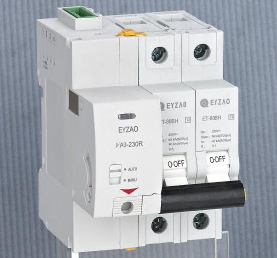
When there is a current fluctuation due to the power supply or external interference, it should also be able to withstand a certain range of overload. Only when there is a large overload current (fault or short circuit) in the circuit, the fuse will act by disconnecting the current to protect the safety of the circuit and avoid the risk of product burnout.
During the process of breaking the circuit by the fuse, an arc will occur at the moment of the fuse melting due to the presence of circuit voltage. High-quality fuses should try to avoid this flying arc. After breaking the circuit, the fuse should be able to withstand the circuit voltage applied at both ends.
If the fuse is damaged by a pulse, its ability to withstand pulses will gradually decrease, and a necessary safety margin must be considered when selecting it. This safety margin refers to the total fuse (action) time of the fuse, which is the sum of the pre-arc time and the arc time.
Therefore, when selecting, attention should be paid to its fuse characteristics and rated current as the basic conditions. In addition, when installing the fuse, the environment around the fuse should be considered. The fuse will only melt when it reaches its own melting heat energy value. If it is in a cold environment, its melting time will change, which must be noted during use.
The role of overvoltage protection devices is completely different from that of overcurrent protection devices. Its main function is to prevent lightning strikes, industrial surge voltage, and electrostatic induction (ESD). They are classified according to the level of charge release.
According to statistics from the American Insurance Company, the proportion of losses caused by lightning strikes in communication and data transmission processing equipment is as high as 13%, and the direct economic losses caused by electrostatic discharge each year are as high as more than 20 billion US dollars. This shows the importance of overvoltage protection.
There are four key points to consider when selecting overvoltage protection devices:
1. The selection of the cutoff voltage Vrwm. The cutoff voltage should be at least 10% higher than the highest operating voltage of the circuit.
2. The selection of the clamping voltage VC. VC refers to the voltage passed through the TVS when in an ESD shock state. It must be smaller than the maximum transient voltage that the protected circuit can withstand.
3. The selection of the surge power Pppm. Different powers have different protection times, such as 600W (10/1000us); 300W (8/20us).
4. The selection of the inter-electrode capacitor. The higher the working frequency of the protected component, the smaller the capacitance of the TVS is required.
Recent Posts



Company
About UsContact UsTerms & ConditionsPrivacy StatementPayment,Shipping & InvoiceRefund & Return PolicyWarranty PolicyFrequently asked questionHolidays for Chinese Mid-Autumn Festival and National Day in 2023


