


 Purchase Protection
Powerful Protection from Payment to Delivery
Secure and Reliable Payment
Money Back Guarantee
Shipping and Delivery
After-Sales Service
Enter the order reference number received by email to check the status or make payment.
Detection and Distinguishing Method of Zener Diode
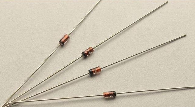
https://chipdatas.com/b/Resistor-color-code-chart-for-beginners.htmlIn electronics, a Zener diode is a specialized diode designed to provide voltage stabilization. It achieves this by utilizing the reverse breakdown state of the diode PN junction, allowing for a wide range of current changes while keeping the voltage relatively constant. Zener diodes are classified based on their breakdown voltage and are primarily used as voltage regulators or voltage reference components. As such, they play a crucial role in electronic circuits. Therefore, it is essential to perform regular maintenance, follow proper usage precautions, and conduct fault detection procedures. In this article, we will provide a detailed guide on how to accurately detect and differentiate Zener diodes.
1. How to Test Zener Diodes with Three Methods?
1.1 Resistance Measurement
The resistance measurement method is commonly used to measure the voltage regulation value of Zener diodes below 10V. This is practical because the maximum voltage of the stacked battery in the analog multimeter is 9V.
To perform this test, follow these steps:
1. Set the multimeter to the RX10K block.
2. Apply a 9V internal power supply to the multimeter, which will put the internal PN junction of the diode in a reverse breakdown state, resulting in a relatively small resistance.
3. Alternatively, you can measure the forward and reverse resistance using the R×1k block on the multimeter. Normally, the reverse resistance is relatively large. If you observe any abnormal needle swings or other irregularities, it indicates poor performance or damage to the Zener diode.
4. Another method is to measure the DC voltage at both ends of the Zener diode using the DC voltage file of the multimeter. If the measured voltage is close to the regulation value, it indicates that the diode is intact. If the voltage deviates significantly from the nominal regulation value or is unstable, it means that the Zener diode is damaged.
5. It's important to note that this method can only measure Zener diodes below 10V and requires an analog multimeter.
You can also use the diode block of the multimeter to measure the quality of the Zener diode. Here's how:
1. Set the multimeter's range switch to the diode position.
2. Touch the positive and negative terminals of the Zener diode with the red and black test pens respectively.
3. If the diode is normal, the multimeter will display a reading of approximately 0.700.
4. Next, swap the test pens and measure the reverse resistance of the Zener diode.
5. If it is a good diode, the reading will be "1". If both the positive and negative readings are either "0.000" or "1" during the measurement, it indicates that the Zener diode is damaged.
1.2 Voltage Measurement
This method is relatively simple. Use the DC voltage file of a digital multimeter to directly measure the output voltage regulation value of the Zener diode. If the measured DC voltage matches the regulation value of the Zener diode, it means that the diode is working normally and is in a stable state.
1.3 Measuring Zener Diode with Megger
For Zener diodes with higher regulated voltages, a megger can be used for detection. Follow these steps:
1. Connect the terminal of the megger to the diode.
2. Shake the handle of the megger at the rated speed.
3. If the megger stabilizes at a certain value, it indicates that the quality of the Zener diode is good. Severe swings suggest a poor Zener diode or a non-Zener diode.
To distinguish between an ordinary diode and a Zener diode, take advantage of the Zener diode's breakdown state. Here's how:
1. Use a 500-volt megger and connect its output terminal in parallel with a digital or analog multimeter.
2. Adjust the voltage of the multimeter to 500 volts.
3. Shake the megger to make the needles deflect in the positive direction. At this point, the red test lead is positive.
4. Connect the two test leads to the two electrodes of the Zener diode under test. If you already know the electrodes, connect the red test lead to the negative electrode of the Zener diode.
5. Shake the megger, and the voltage value measured on the meter will be the regulation voltage value, which is the voltage stabilization value of the Zener diode.
6. If you don't know the electrodes of the Zener diode, shake the megger and observe the voltage. If there is no voltage (0.5 volt), change the test lead and test again.
7. This method is suitable for detecting Zener diodes below 200 volts. If the measured voltage exceeds 200 volts, it may not be a Zener diode.

Zener Diode Symbol
2. How to Measure the Leakage of Zener Diode?
Zener diodes are commonly tested for leakage using an oscilloscope. To do this, a gradually increasing reverse voltage is applied to both ends of the Zener diode. As the voltage reaches the critical point, the leakage current of the diode gradually increases. It is important to note that the higher the voltage, the greater the leakage current will be.
While a multimeter can be used to measure the forward and reverse resistance of a Zener diode, it can only provide a rough estimation of its quality. Therefore, using an oscilloscope for leakage testing is a more reliable method.
3. How to Figure the Polarity of the Zener Diode?
When it comes to determining the polarity of Zener diodes, there are a few visual cues to consider. In metal-encapsulated Zener diodes, the positive pole of the tube body appears flat, while the negative end is semicircular. On the other hand, plastic-encapsulated Zener diodes often have a color mark indicating the negative pole, with the opposite end being the positive pole.
If the polarity is unclear or there are no visual indicators, a multimeter can be used to determine the polarity. The measurement method is similar to testing ordinary diodes. Set the multimeter to the R×1k range and connect the two test leads to the two electrodes of the Zener diode. Take a measurement and note the result. Then, reverse the test leads and take another measurement. Compare the two results and choose the one with the smaller resistance value. The black test lead should be connected to the anode of the Zener diode, while the red test lead should be connected to the cathode.
4. How to Identify Color Code Zener Diode?
Zener diodes are commonly marked with color codes to indicate their models and parameters. Detailed information about these markings can usually be found in the component manual. It's important to note that Zener diodes are small in size and low in power, typically operating within a voltage range of 10V or lower. Due to their delicate nature, they can be easily damaged if mishandled.
The appearance of Zener diodes is quite similar to that of color code resistors, which can lead to confusion. However, the color ring on a Zener diode serves two purposes. Firstly, it represents a numerical value. Secondly, it indicates the number of decimal places in the value (usually denoted by the color brown). This can also be interpreted as the magnification factor, with a value of ×10 (or 10 raised to the power of -1). The specific color associated with a particular value is the same as the color code used for resistors.
To accurately identify and differentiate Zener diodes, it is recommended to consult the component manual for detailed information on the color code markings. Additionally, using an oscilloscope to measure the leakage current of the Zener diode and a multimeter to determine its polarity can provide further assistance in the identification process. Furthermore, the physical appearance of the Zener diode, such as the type of packaging (metal or plastic), can also offer clues about its polarity.
5. How to Distinguish Zener Diodes and Ordinary Diodes?
The Zener diode has a forward characteristic similar to that of a regular diode, where the voltage is smaller than the breakdown voltage and the diode is in an open state. To determine if a diode is a Zener diode, you can follow these steps:
1. Set the multimeter to the R×1k range.
2. Connect the test leads to the positive and negative terminals of the diode.
3. Connect the black test lead to the cathode (negative terminal) of the diode and the red test lead to the anode (positive terminal).
4. Measure the reverse resistance of the PN junction. If the reading is very high and the meter's needle doesn't deflect, it indicates that the diode is not conducting in reverse.
5. Switch the multimeter to the R×10k range.
6. If the needle deflects to the right by a certain angle, it suggests that the diode being measured is a Zener diode.
7. If the needle doesn't deflect, it means that the diode may not be a Zener diode. Please note that this method is only suitable for Zener diodes with a voltage rating lower than the battery voltage of the multimeter in the R×10k range.
The principle behind this measurement method is that the battery voltage in the R×10k range is higher than that in the R×1k range. If the Zener diode's breakdown voltage is lower than the battery voltage, the PN junction will experience breakdown, resulting in a significant drop in resistance. Regular diodes have a higher reverse withstand voltage, so the battery voltage in the R×10k range is not enough to cause breakdown. Additionally, if the Zener diode's voltage rating is higher than the battery voltage of the multimeter, the needle will not deflect, and the type of diode cannot be determined using this method.
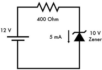
Zener Diode Voltage Regulator Circuit
6. FAQ
1. How do you identify a 12V Zener diode?
To identify a 12V Zener diode, you can use a multimeter. Place the diode across the meter probes in both directions. If the meter reads a low voltage (under 1V) in one direction and less than 18V in the other direction, then the diode is likely to be a Zener diode. The voltage displayed on the multimeter is the Zener diode voltage.
2. How do you know if a Zener diode is bad?
To determine if a Zener diode is bad, you can measure the reverse-biased voltage on the diode using a multimeter. Switch the multimeter probes and place the positive lead on the marked or cathode side of the diode, and the negative lead on the unmarked or anode side. If you get a reading indicating infinite resistance or no current flow, then the Zener diode is likely bad.
3. What is the difference between a diode and a Zener diode?
A diode is a semiconductor device that conducts current in one direction only. On the other hand, a Zener diode is a semiconductor device that conducts current in both forward and reverse biased conditions. This means that a Zener diode can allow current flow in the reverse direction once it reaches a specific voltage known as the Zener voltage.
4. What happens when a Zener diode is shorted?
When a Zener diode is shorted, it typically fails by becoming short circuited in reverse bias. Before it becomes short circuited, the terminal voltage of the Zener diode increases, behaving like an open circuit for a few seconds. After that, it permanently goes into a short circuit state.
5. How do you test a Zener diode?
To test a Zener diode, you can measure the resistance between the terminals 1/4/5/8 and one of the four earth terminals 2/3/6/7. A healthy Zener diode should have an extremely high resistance at each of the terminals 1/4/5/8. The measuring instrument may not show any reaction if the Zener diode is in good condition.
6. Why is a Zener diode reverse biased?
A Zener diode is heavily doped, which means it has a high concentration of impurities compared to a regular diode. When a Zener diode is reverse biased, the junction potential increases. This high breakdown voltage allows the Zener diode to handle high voltages. As the reverse voltage increases, the reverse current also increases significantly at a certain reverse voltage.
7. What happens when a Zener diode is forward biased?
When a Zener diode is forward biased, it allows a large amount of electric current to flow through it and blocks only a small amount of electric current. The Zener diode is heavily doped compared to a normal p-n junction diode, resulting in a very thin depletion region.
8. How do I identify an SMD Zener diode?
To identify an SMD Zener diode, you can refer to the markings on the package. Look for symbols, such as the diode symbol, the length of the lead, color wheels, or color spots. The positive and negative poles of the voltage regulation SMD diode are also divided, similar to general-purpose SMD diodes.


Company
About UsContact UsTerms & ConditionsPrivacy StatementPayment,Shipping & InvoiceRefund & Return PolicyWarranty PolicyFrequently asked questionHolidays for Chinese Mid-Autumn Festival and National Day in 2023 Copyright © 2022-2024 Power by Chipdatas Trading Limited. All Rights Reserved.