Detailed explanation of diode classification and detection methods
Diode is an electronic component with two electrodes, allowing current to flow in only one direction, widely used in rectifier circuits. Varicap diode is used as an electronic adjustable capacitor.
Classification of Diodes
There are many types of diodes. According to the semiconductor materials used, they can be divided into germanium diodes (Ge diodes) and silicon diodes (Si diodes). According to their different uses, they can be divided into detection diodes, rectifier diodes, voltage regulator diodes, switch diodes, isolation diodes, Schottky diodes, light-emitting diodes, silicon power switch diodes, rotating diodes, etc. According to the core structure, they can be divided into point-contact diodes, surface-contact diodes, and planar diodes.
Methods of Diode Detection
Detection of Low Power Crystal Diodes
A. Discriminate the positive and negative electrodes
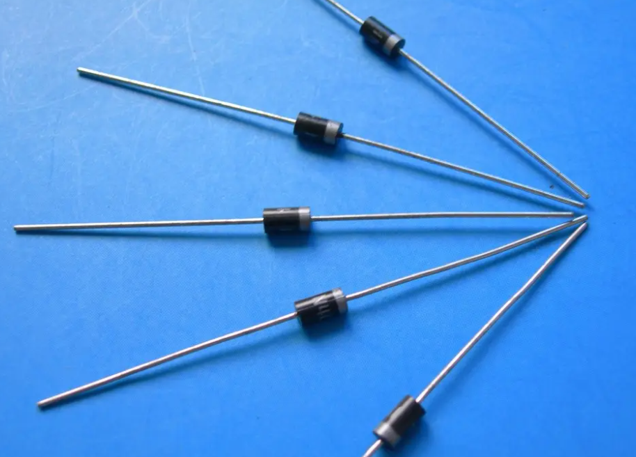
(a) Observe the symbol mark on the shell. Usually, the symbol of the diode is marked on the shell, and the end with a triangular arrow is the positive electrode, and the other end is the negative electrode.
(b) Observe the color dot on the shell. On the shell of a point-contact diode, there is usually a polarity color dot (white or red). Generally, the end with the colored dot is the positive electrode. Some diodes are marked with a colored ring, and the end with the colored ring is the negative electrode.
(c) Take the first measurement with the smaller resistance value as the criterion. The end connected to the black test pen is the positive electrode, and the end connected to the red test pen is the negative electrode.
(d) Observe the diode shell, and the end with a silver band is the negative electrode.
B. Detection of the highest reverse breakdown voltage. For AC power, the highest reverse operating voltage is the AC peak voltage that the diode can withstand.
Detection of Bidirectional Trigger Diodes
Set the multimeter to the corresponding DC voltage range. The test voltage is provided by the megohmmeter. During the test, shake the megohmmeter, and use the same method as the multimeter to measure the VBR value. Finally, compare VBO with VBR. The smaller the absolute difference between the two, the better the symmetry of the bidirectional trigger diode being tested.
Detection of Transient Voltage Suppression Diodes (TVS)
A. Use a multimeter to measure the quality of the diode. For unipolar TVS, according to the method of measuring ordinary diodes, the forward and reverse resistance can be measured. Generally, the forward resistance is about 4kΩ, and the reverse resistance is infinite. For bipolar TVS, the resistance value between its two pins should be infinite when the red and black test pens are arbitrarily interchanged. Otherwise, the performance of the diode is poor or has been damaged.
Detection of High-Frequency Variable Resistance Diodes
The difference in appearance between high-frequency variable resistance diodes and ordinary diodes lies in the color of their color code. The color code of ordinary diodes is generally black, while the color code of high-frequency variable resistance diodes is light-colored. Their polarity rule is similar to that of ordinary diodes, that is, the end with a green ring is the negative electrode, and the end without a green ring is the positive electrode.
Detection of Varicap Diodes
Reverse the red and black test pens of the multimeter for measurement. The resistance value between the two pins of the varicap diode should be infinite. If during the measurement, the pointer of the multimeter swings slightly to the right or the resistance value is zero, it indicates that the varicap diode being tested has a leakage fault or has been damaged.
Detection of Monochrome Light-Emitting Diodes
Attach a 1.5V dry battery outside the multimeter and set the multimeter to the R×10 or R×100 range. This connection is equivalent to adding a 1.5V voltage to the multimeter in series, increasing the test voltage to 3V (the turn-on voltage of the light-emitting diode is 2V). During the test, use the two test pens of the multimeter to alternately contact the two pins of the light-emitting diode. If the diode is functioning properly, it will emit light normally at least once. The end connected to the black test pen is the positive electrode, and the end connected to the red test pen is the negative electrode.


Company
About UsContact UsTerms & ConditionsPrivacy StatementPayment,Shipping & InvoiceRefund & Return PolicyWarranty PolicyFrequently asked questionHolidays for Chinese Mid-Autumn Festival and National Day in 2023 Copyright © 2022-2024 Power by Chipdatas Trading Limited. All Rights Reserved.