


 Purchase Protection
Powerful Protection from Payment to Delivery
Secure and Reliable Payment
Money Back Guarantee
Shipping and Delivery
After-Sales Service
Enter the order reference number received by email to check the status or make payment.
Choosing the Right Diode Rectifier for Your Circuit
The rectifier diode is a semiconductor device used to convert AC (alternating current) into DC (direct current). It typically consists of a PN junction with two terminals: a positive electrode and a negative electrode. Its most important characteristic is its ability to conduct current in only one direction. In electronic circuits, rectifier diodes exhibit high breakdown voltage, low reverse leakage current, and good performance at high temperatures. They are commonly made from semiconductor materials such as germanium or silicon.
For high-voltage and high-power applications, rectifier diodes are often constructed using high-purity single crystal silicon, which is more prone to reverse breakdown with increased doping. These diodes have a larger junction area and can handle large currents, sometimes reaching thousands of amperes. However, their operating frequency is typically not high, generally below tens of kilohertz.
Rectifier diodes find primary use in various low-frequency half-wave rectifier circuits. For full-wave rectification, multiple diodes need to be connected to form a rectifier bridge.
1. Common Parameters
The rectifier diode is a semiconductor device that utilizes the unidirectional conductivity of the PN junction to convert alternating current into pulsating direct current. It is typically composed of a PN junction with two terminals, namely the anode and the cathode. Rectifier diodes are characterized by their high breakdown voltage, low reverse leakage current, and good high-temperature performance. They are commonly made from materials such as semiconductor germanium or silicon. For high voltage and high power applications, rectifier diodes made from high-purity single crystal silicon are more commonly used as these materials are prone to reverse breakdown when heavily doped. These devices have a large junction area, allowing them to handle large currents (up to several thousand amperes), but their operating frequency is generally low, typically below several tens of kilohertz. Rectifier diodes are primarily used in various low-frequency half-wave rectifier circuits, and if full-wave rectification is required, multiple diodes need to be connected to form a rectifier bridge.
Rectifier diodes have several important parameters, in addition to the maximum rectifier current, which is the main parameter used to select a rectifier diode. Other important parameters include:
1. Maximum average rectified current (IF): This refers to the maximum forward average current that the diode can handle during long-term operation. The current is determined by the PN junction area and the heat dissipation conditions. It is important to note that the average current passing through the diode should not exceed this value, taking into account heat dissipation.
2. Maximum reverse working voltage (VR): This refers to the maximum reverse voltage that can be applied across the diode. If the applied voltage exceeds this value, the reverse current (IR) will sharply increase, leading to the destruction of the diode's unidirectional conductivity and causing reverse breakdown. Usually, VR is taken as half of the reverse breakdown voltage (VB).
3. Maximum reverse current (IR): This is the maximum reverse current allowed to flow through the diode under the highest reverse working voltage. This parameter reflects the quality of the diode's unidirectional conductivity. A smaller current value indicates better diode quality.
4. Breakdown voltage (VB): This refers to the voltage value at the sharp bend point of the diode's reverse volt-ampere characteristic curve. In the case of a soft characteristic curve, it refers to the voltage value under a given reverse leakage current condition.
5. Maximum operating frequency (fm): This is the highest frequency at which the diode can operate under normal conditions. It is mainly determined by the junction capacitance and diffusion capacitance of the PN junction. If the operating frequency exceeds fm, the diode's unidirectional conductivity may not be well reflected.
6. Reverse recovery time (trr): This refers to the time it takes for the diode to recover from the reverse bias state under specified load, forward current, and maximum reverse transient voltage.
7. Zero-bias capacitance (CO): This refers to the sum of the diffusion capacitance and junction capacitance when the voltage across the diode is zero.
It is worth noting that due to manufacturing process limitations, even diodes of the same type can have a large dispersion of their parameters. The parameters provided in the manual are often given within a range. If the test conditions change, the corresponding parameters will also change. For example, the reverse current (IR) of the 1N5200 series silicon plastic rectifier diode measured at 25°C is less than 10uA, while at 100°C, IR becomes less than 500uA.
2. Rectifier Diodes Selection
Rectifier diodes are commonly used in power rectifier circuits and are typically planar silicon diodes. When choosing a rectifier diode, it is important to consider parameters such as maximum rectifier current, maximum reverse working current, cut-off frequency, and reverse recovery time.
For ordinary series stabilized power supply circuits, the rectifier diode does not require a high reverse recovery time or cut-off frequency. It is sufficient to select a rectifier diode that meets the circuit's requirements for maximum rectified current and maximum reverse working current.
However, for rectifier circuits in switching regulated power supplies and pulse rectifier circuits, it is necessary to use rectifier diodes with higher operating frequencies and shorter reverse recovery times. Examples of such diodes include the RU series, EU series, V series, 1SR series, or alternatively, fast recovery diodes or Schottky rectifier diodes.
3. Rectifier Common Failures
3.1 Insufficient lightning protection and inadequate overvoltage protection measures are major factors contributing to rectifier device failure. The absence of lightning protection and overvoltage protection devices, as well as inadequate routine maintenance, can leave the rectifier device vulnerable to damage.
3.2 Poor operating conditions can significantly impact the longevity of rectifier devices. In the case of indirect drive generator sets, incorrect speed ratio calculations or the use of belt pulleys with incompatible diameters can result in the generator running at high speeds for extended periods. This prolonged exposure to higher voltages accelerates the aging process of the rectifier, leading to premature breakdown.
3.3 Inadequate operation management practices can also contribute to rectifier device failures. Failure to promptly address load failures or diode breakdowns can exacerbate the damage and increase the likelihood of complete failure.
3.4 The installation and manufacturing processes of the equipment can play a crucial role in the performance and durability of rectifier devices. Prolonged operation under conditions of significant vibration, often experienced by generator sets, can negatively impact the operation of rectifier tubes. Additionally, unstable generator set speeds can cause voltage fluctuations, further accelerating aging and damage to the rectifier tubes.
3.5 Mismatched specifications and models of rectifier tubes can lead to their failure. Incorrectly replacing rectifier tubes with those that do not meet the required working parameters or improperly wiring them can result in breakdowns and subsequent damage.
3.6 The rectifier tubes may have an inadequate safety margin, making them susceptible to damage from overvoltage or transient overcurrents occurring in the generator excitation circuit. Insufficient safety margins prevent the rectifier tubes from withstanding these extreme conditions, leading to their failure.

4. Rectifier Diodes Detection
Here is a more general and simplified method to test rectifier diodes. Follow these steps:
1. Remove all rectifier diodes from the circuit.
2. Use the 100×R or 1000×R ohm range on a multimeter to measure the two leads of the rectifier diode. Make sure to adjust and test twice for accuracy.
3. If the resistance values measured twice are significantly different, such as a high resistance value of a few hundred kΩ to infinity or a low resistance value of a few hundred Ω or less, it indicates that the diode is functioning properly (except under special circumstances).
4. If the resistance values measured twice are almost the same and the resistance value is very small, it means that the diode has experienced breakdown and is no longer usable.
5. Additionally, if the resistance values measured twice are both infinite, it suggests that the diode has an internal disconnection and cannot be used.
By following these steps, you can effectively test the rectifier diodes and determine their usability.
5. Rectifier Diode Replacement
5.1 Replacement Rules
When the rectifier diode is damaged, you should replace it with the same model or another model with the same parameters.
Generally, rectifier diodes with higher voltage withstand (reverse voltage) can be substituted for rectifier diodes with lower voltage withstand, while rectifier diodes with lower voltage withstand cannot be replaced with rectifier diodes with higher voltage withstand. A diode with a higher rectification current value can be substituted for a diode with a lower rectification current value, while a diode with a lower rectification current value cannot be substituted for a diode with a higher rectification current value.
5.2 Commonly Used Rectifier Models List
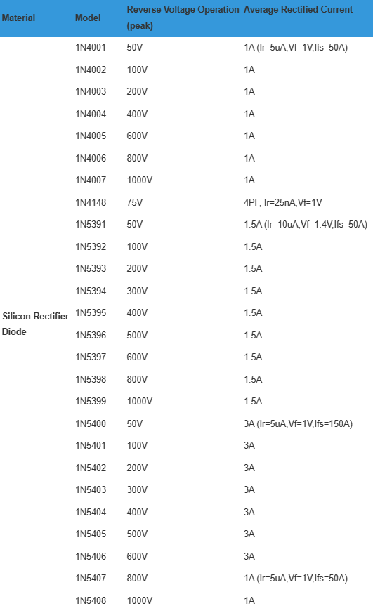
6. Rectifier Diode Circuit Types
The power grid supplies users with alternating current (AC), but many electrical devices require direct current (DC). Rectification is the process of converting AC into DC. This can be achieved by using rectifier circuits composed of crystal diodes. In this article, we will discuss three main rectifier circuits: the half-wave rectifier circuit, the full-wave rectifier circuit, and the bridge rectifier circuit.
6.1 Half-Wave Rectifier Circuit
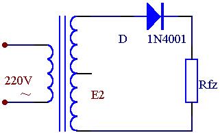
The half-wave rectifier circuit is the simplest rectifier circuit. It consists of a power transformer (B), a rectifier diode (D), and a load resistor (Rfz). The transformer converts the voltage into the required alternating voltage (e2), and then the diode transforms the AC into pulsating DC.
The voltage e2 from the transformer is a sine wave voltage that changes direction and magnitude over time. In the 0 to π/2 time period, e2 is a positive half cycle, where the upper end of the transformer is positive and the lower end is negative. The diode is in forward conductive conduction during this time, allowing e2 to pass through and reach the load resistor Rfz. In the π/2 to π time period, e2 is in the negative half cycle, where the lower end of the transformer secondary is positive and the upper end is negative. The diode does not conduct in this case, and there is no voltage on Rfz.
This process repeats in the π to 2π time period and so on, resulting in a pulsating DC voltage across Rfz. This pulsating DC has a single direction but varies with time.
The half-wave rectification method, which removes half of the AC cycle and leaves only half a cycle, is not very efficient as it wastes half of the AC power. Therefore, the half-wave rectifier diode is commonly used in high voltage and low current applications and is rarely used in general radio devices.
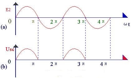
6.2 Full-Wave Rectifier Circuit

By making some adjustments to the rectifier circuit, we can obtain a full-wave rectifier circuit. This circuit is a combination of two half-wave rectifier circuits. A tap is drawn in the middle of the secondary coil of the transformer to divide it into two symmetrical windings, resulting in two voltages (e2a and e2b) of equal size but opposite polarity.
The working principle of the full-wave rectifier circuit can be illustrated using waveform diagrams. In the 0 to π time period, e2a is a positive voltage to D1, which turns it on and creates an up-positive and down-negative voltage across Rfz. At the same time, e2b is a reverse voltage to D2, which keeps it from conducting. In the π to 2π time period, e2b is a positive voltage to D2, which turns it on and maintains the up-positive and down-negative voltage across Rfz. Meanwhile, e2a is a reverse voltage to D1, keeping it from conducting.
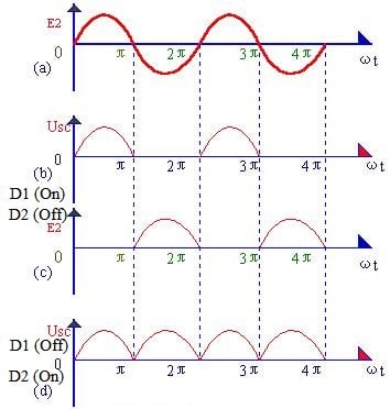
By repeating this process, the load resistor Rfz experiences current in the same direction during both the positive and negative half cycles, resulting in full-wave rectification. This method utilizes both the positive and negative half cycles of the AC waveform, significantly improving rectification efficiency.
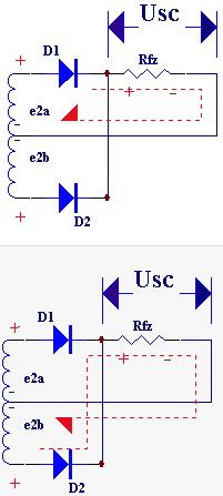
The full-wave rectifier circuit requires a transformer with a center tap on the secondary coil to achieve symmetry. This adds complexity to the production process. Additionally, each rectifier diode in this circuit must withstand a maximum reverse voltage that is twice the maximum value of the transformer secondary voltage.
6.3 Bridge Rectifier Circuit

The bridge rectifier circuit is the most commonly used rectification circuit. It overcomes some of the shortcomings of the full-wave rectifier circuit by forming a bridge structure using four diodes.

In this circuit, when e2 is in the positive half cycle, D1 and D3 conduct while D2 and D4 do not. This creates a loop in the circuit consisting of e2, D1, Rfz, and D3, resulting in a positive and negative half-wave rectified voltage across Rfz. When e2 is in the negative half cycle, D2 and D4 conduct while D1 and D3 do not. This creates another loop consisting of e2, D2, Rfz, and D4, producing another half-wave rectified voltage across Rfz.

By repeating this process, a full-wave rectified voltage is obtained across Rfz. The waveform diagram is the same as that of the full-wave rectifier circuit. It is worth noting that the reverse voltage of each diode in the bridge circuit is equal to the maximum value of the transformer secondary voltage, which is half the value of the full-wave rectifier circuit.
7. High-frequency Rectifier Diodes
The rectifier diode used in a switching power supply should have low forward voltage drop and fast recovery characteristics, as well as sufficient output power. There are three types of high-frequency diodes that can be used: fast recovery rectifier diodes, ultra-fast recovery rectifier diodes, and Schottky diode rectifiers.
Fast recovery and ultra-fast recovery rectifier diodes have moderate to high forward voltage drop, typically ranging from 0.8 to 1.2V. These diodes also have higher cut-off voltage parameters, making them suitable for use in low-power auxiliary power circuits with output voltages around 12V.
Compared to general rectifier diodes, fast recovery and ultra-fast recovery rectifier diodes have significantly reduced reverse recovery time, typically in the nanosecond range. This greatly improves the efficiency of the power supply. When selecting a fast recovery rectifier diode, it is recommended to choose one with a reverse recovery time of at least 1/3 of the rise time of the switching transistor. These diodes also help reduce switching voltage spikes, which can affect the ripple of the output DC voltage.
Whether heat sinks are required for fast recovery and ultra-fast recovery rectifier diodes used in switching power supplies depends on the maximum power of the circuit. The allowable junction temperature during manufacturing is typically 175°C. The manufacturer provides technical parameters for the designer to calculate the maximum output operating current, voltage, and case temperature. Schottky rectifier diodes, on the other hand, have a very low forward voltage drop of about 0.4V, which decreases as the junction temperature increases. They are particularly suitable for low-voltage output circuits around 5V. Schottky diodes have negligible reverse recovery time since they are majority carrier devices. The stored charge of the minority carrier does not need to be removed during the switching process.
Schottky rectifier diodes have two major shortcomings. First, their reverse breakdown voltage tolerance is low, typically around 100V. Second, they have a large reverse leakage current, making them more susceptible to heat breakdown compared to other types of rectifier devices. However, these shortcomings can be overcome by adding a transient overvoltage protection circuit and properly controlling the junction temperature.
8. FAQ
1. How does a rectifier diode work?
A rectifier diode is a device that converts Alternating Current (AC) into Direct Current (DC) by allowing current to flow in only one direction. When an AC voltage is applied to the diode, it allows current to flow during the positive half-cycle and blocks current during the negative half-cycle. This process effectively converts the alternating current into a direct current source.
2. What is the function of a rectifier diode?
The main function of a rectifier diode is to convert Alternating Current (AC), which periodically reverses direction, into Direct Current (DC). It allows current to flow in one direction while blocking current in the opposite direction, thus rectifying the AC signal into a DC signal.
3. What is the function of a diode in a rectifier circuit?
A diode in a rectifier circuit acts as a one-way valve for electric current. It allows current to flow in the forward direction (from anode to cathode) when the voltage across it is positive, effectively rectifying the AC voltage. During the reverse direction (negative voltage), the diode blocks current flow, ensuring that only the positive half-cycle of the AC voltage is converted into DC.
4. Which diode is used as a rectifier?
A rectifier typically uses semiconductor diodes to perform the conversion of AC to DC. These diodes are designed to handle the high currents and voltage levels associated with rectification. Commonly used rectifier diodes include standard silicon diodes, fast recovery diodes, and Schottky diodes.
5. What are the limitations of a diode rectifier?
One limitation of a diode rectifier is that it requires a minimum voltage drop across the diode to function properly. This voltage drop can cause power loss and reduce the efficiency of the rectifier. Additionally, diode rectifiers are not suitable for applications requiring very low voltage rectification due to the voltage drop across the diode.
6. What is the ideal efficiency of a rectifier diode?
The efficiency of a rectifier diode refers to the ratio of DC output power to AC input power. The ideal efficiency of a full-wave rectifier is 81.2%, which means that 81.2% of the input power is converted into usable DC power.
7. What is a fast recovery rectifier?
A fast recovery rectifier is a type of diode that is designed to have a short reverse recovery time. This makes it suitable for rectifying high-frequency AC signals. Fast recovery diodes are commonly used in applications where ultra-high switching speed is required.
8. What is a fast recovery diode?
A fast recovery diode, also known as an FRD, is a semiconductor device with a short reverse recovery time. It is designed specifically for rectification purposes at high frequencies. Fast recovery diodes have ultra-high switching speeds and are commonly used in rectifiers.
9. What is an ultra-fast recovery diode?
An ultra-fast recovery diode is a diode that recovers from the reverse-biased state much faster than a standard diode. It typically recovers ten times faster than a standard diode, and the term "ultra-fast" is used when the recovery time is more than fifty times faster. These diodes are used in applications that require extremely fast switching speeds.
10. What is the difference between a Schottky diode and a rectifier diode?
A Schottky diode, also known as a barrier diode, is primarily used in low voltage circuits because it has a lower forward voltage drop compared to a standard rectifier diode. The forward voltage drop of a Schottky diode is typically in the range of 0.25 to 0.5 volts, while a rectifier diode has a forward voltage drop of around 0.7 volts.
11. What is a Schottky barrier rectifier?
A Schottky barrier rectifier, named after the German physicist Walter H. Schottky, is a type of semiconductor diode that incorporates a metal-semiconductor junction. It is known for its low-forward voltage drop and rapid switching characteristics. The Schottky diode is one of the oldest semiconductor devices and is widely used in various applications.


Company
About UsContact UsTerms & ConditionsPrivacy StatementPayment,Shipping & InvoiceRefund & Return PolicyWarranty PolicyFrequently asked questionHolidays for Chinese Mid-Autumn Festival and National Day in 2023 Copyright © 2022-2024 Power by Chipdatas Trading Limited. All Rights Reserved.