Powerful Protection from Payment to Delivery
Secure and Reliable Payment
Money Back Guarantee
Shipping and Delivery
After-Sales Service
Characteristics and Applications of Capacitors
A capacitor is a widely used electronic component that has the ability to store and release electricity. It is known for its unique characteristic of allowing Alternating Current (AC) to pass through while blocking Direct Current (DC). This feature raises several questions: What are the differences between AC and DC capacitors? Can AC and DC capacitors be used interchangeably? How do batteries differ from capacitors? Why can't capacitors be used as a substitute for batteries? Additionally, if you are interested in capacitor calculations, you will also find information on the time constant for discharging a capacitor. Let's explore these questions and find the answers.
1 Why Can the Battery (DC) Charge the Capacitors?
In circuit analysis, there are two types of circuit responses: zero-input response and zero-state response. The zero-input response refers to the case when the input signal is zero, while the zero-state response means that the energy storage elements and various power sources in the circuit are in a zero state.
When analyzing the zero-state response, the voltage source is short-circuited and the current source is disconnected. For a capacitor, during the zero-state response, it can be treated as a voltage source with zero voltage, thus equivalent to a short circuit. Let's analyze the following circuit: Figure 1 shows the circuit structure: power source E, internal resistance r, switch QF, capacitor C, and resistor R. When the switch QF is open, let's take a look at the current Ic and the voltage Uc across the capacitor:
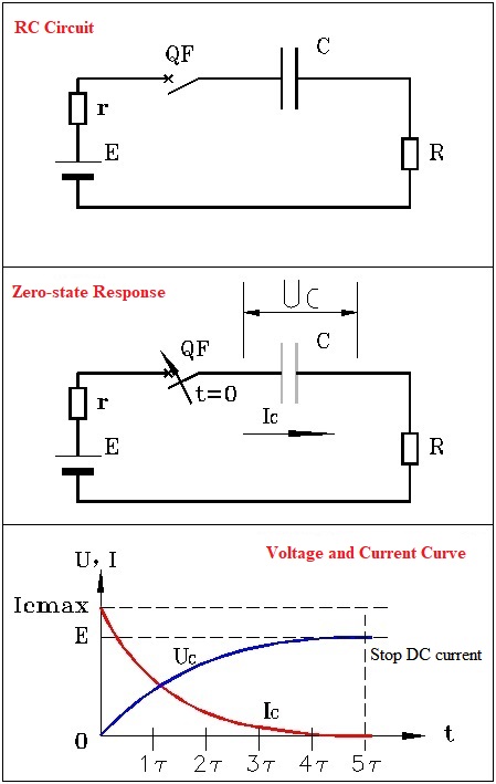
Figure 1. Zero-input response and zero-state response curves
We can see that at t=0, the current through the capacitor is maximum. At this moment, the capacitor is equivalent to a voltage source with zero voltage, and the power source E needs to charge it through the internal resistance r. Therefore, we can understand that it is actually a short circuit, and the maximum charging current at t=0 is Icmax. From the graph, it can be seen that after 5τ, the current becomes zero and the voltage has charged to a value close to E. After this point, the current through the capacitor will no longer change, and the capacitor acts as a barrier to direct current. From the graph, it can be seen that the charging process of the capacitor can be divided into two parts: transient transition and steady-state.
Next, let's analyze the transient transition in detail. Let's first look at the product of the resistance value r and the capacitance value C, which is RC. The resistance value equals voltage divided by current, the capacitance value equals charge divided by voltage, and the charge equals current divided by time. So we have: RC, where T is called the time constant, usually represented by τ.
Therefore, the current flowing through the capacitor is: Ic
Here, the exponential function has an exponent equal to the ratio of time to the time constant, so it is a pure number. When time equals 0, Ic=Icmax; when time equals 5τ, the value of the exponential function is 6.738×10⁻³. Substituting into the above formula, we get the current at this time: I
The expression for the capacitor voltage Uc at this time is: Uc
Note: In theory, the voltage on the capacitor should charge to ER/(R+r), but since the impedance of the capacitor is infinite in steady state, its voltage can charge to E.
From here, we can see that the so-called barrier to direct current by the capacitor actually refers to its steady-state characteristics. In steady state, the equivalent impedance of the capacitor is infinite, and direct current cannot pass through it, so the current is zero, with at most a very small leakage current. In the transient state, the capacitor can conduct current, and in the initial stage, due to the capacitive nature, the current is similar to a voltage source, and its characteristics are almost short-circuit, so the initial current value is maximum.
If our power source is not a battery but a square wave pulse generator, what is the voltage across the resistor R after the capacitor?
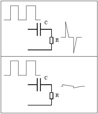
Figure 2. Square wave pulse generator
Figure 2 represents a case with a small time constant, reflecting the impulse response of the capacitor; the image below represents a case with a large time constant, reflecting the abundant applications of these two effects.
If our power source is an AC voltage, what is the voltage across the resistor R after the capacitor?
When discussing the response of a capacitor to an AC current range, we need to temporarily review the first graph. From the graph, it can be seen that when the current reaches its maximum value, the voltage reaches its minimum value; however, when the current reaches its minimum value, the voltage reaches its maximum value. Why is this so?
The capacitance value equals the charge divided by the voltage, that is, C=Q/U=It/U, from which we obtain the current: I=CU/t. The voltage Uc on the capacitor is actually changing, it is a function of time, so the above formula can be written as: Capacitor I
This formula is very important, as it is the key to understanding the response of a capacitor under the influence of an AC voltage.
The AC voltage can be expressed as , substituting it into the expression for the capacitor current, we get: Ui
We can see that when the voltage is zero, the current reaches its maximum value. In other words, for an AC power source, the current through the capacitor leads the voltage by 90 degrees. It reveals the expression of the capacitor under the AC voltage.
The capacitor is used to block direct current, but it only has this performance in steady state. When the DC power source changes rapidly, that is, the power source continuously goes from zero to the maximum value and then back to zero. In this cycle, we can see that the capacitor not only does not block direct current, but also becomes a component with almost zero impedance.
In fact, from the capacitive reactance (Xc), it can be known that as the frequency of the power source increases, the capacitive reactance increases linearly with the frequency. When we charge the capacitor with a sufficient DC power source, the charging voltage of the capacitor can reach the same level as the electromotive force of the power source. The key here is that the capacitor is an energy storage element.
2 DC Capacitors vs AC Capacitors
1) DC capacitors and AC capacitors: AC capacitors, also known as non-polarized capacitors, do not have a specific polarity. This means they can be used in both AC and DC circuits. On the other hand, DC capacitors are polarized and have a higher capacitance but lower voltage withstand capacity. It's important to note that both types of capacitors will experience some level of loss over time.
2) Mobility of DC capacitors and AC capacitors: In a DC capacitor, one end always maintains a high voltage while the current flows in a single direction. In contrast, AC capacitors are connected to an AC power supply where the voltage levels constantly change. This allows the current to flow in both directions, from point A to point B, or from point B to point A, and adjust over time.
3) Difference between direct current and alternating current: Alternating current can be understood as two groups of direct current that take turns influencing the load. This can be visualized as the vector sum of two groups of direct current in different time periods. On the other hand, direct current flows continuously in one direction over a short enough time period, effectively behaving as a single group of direct current.
3 Battery or Capacitor?
Capacitors and batteries are both electrical components used for energy storage, but they have fundamental differences. Let's explore these differences in more detail:
1) Chemical Energy vs Electrical Energy:
Batteries store chemical energy and convert it into electrical energy for output. On the other hand, capacitors store electrical energy using two plates to determine their capacity. While batteries undergo a chemical change, capacitors undergo a physical change. The main function of a capacitor is to store electric charge, which can be charged and discharged like a battery, but without any chemical reactions.
2) Capacity:
Batteries have a higher storage capacity for electrical energy compared to capacitors. Capacitors store a relatively smaller amount of energy.
3) Charge and Discharge:
The charging and discharging characteristics of batteries and capacitors differ. Capacitors can be charged and discharged in a matter of seconds or minutes, whereas batteries typically require several hours to charge. Additionally, capacitors can undergo charging and discharging cycles tens of millions of times, while batteries usually have a limited number of charging and discharging cycles, typically in the range of a few hundred to a thousand.

Figure 3. Charge and Discharge Curve
4) Functions:
Capacitors and batteries serve different purposes. Capacitors are versatile and can be used for various applications such as coupling, blocking, filtering, phase shifting, RC (resistor-capacitor) circuits, LC (inductor-capacitor) resonance, and as energy storage components for instantaneous large current discharge. On the other hand, batteries are primarily used as a power source.
4 Calculate the Time Constant for the Discharge of the Capacitors?
Let’s review the calculation formula for the charge and discharge time of a capacitor. Suppose there is a power supply that charges the capacitor C through the resistor R. V0 represents the initial voltage value on the capacitor, Vu represents the voltage value after the capacitor is fully charged, and Vt represents the voltage value at any time t on the capacitor. The following calculation formula can be used:
Vt = V0 + (Vu – V0) * [1 – exp( -t/RC)]
If the initial voltage on the capacitor is 0, the formula can be simplified to:
Vt = Vu * [1 – exp( -t/RC)]...Charging formula
From the above formula, we can observe that the index value can only approach 0 infinitely but will never be equal to 0. Therefore, it takes an infinite amount of time for the capacitor to be fully charged.
Here are some key observations based on the formula:
🔺 When t = RC, Vt = 0.63Vu
🔺 When t = 2RC, Vt = 0.86Vu
🔺 When t = 3RC, Vt = 0.95Vu
🔺 When t = 4RC, Vt = 0.98Vu
🔺 When t = 5RC, Vt = 0.99Vu
From the above observations, we can conclude that after approximately 3 to 5 time constants (RCs), the charging process is essentially complete. Once the capacitor is fully charged, if the power supply is short-circuited, the capacitor C will discharge through R. At any time t during the discharging process, the voltage on the capacitor can be calculated using the following formula:
Vt = Vu * exp( -t/RC)...Discharging formula
These formulas provide a mathematical understanding of the charge and discharge behavior of capacitors.
5 FAQ
1. Can a capacitor be used as a battery?
A capacitor can store energy when a voltage is applied across its conductors. It operates similarly to a battery in that it can be charged up if a potential difference is applied that exceeds its current charge.
2. Why can't capacitors replace batteries?
Capacitors have lower energy density compared to batteries, which means they cannot provide large amounts of energy. However, capacitors are useful for short-duration power requirements because they can be charged or discharged at a higher rate than batteries.
3. What is the difference between a battery and a supercapacitor?
Batteries are better at storing energy, while supercapacitors excel in terms of power. This means that supercapacitors can discharge their stored energy quickly, while batteries can store more energy in the same amount of material.
4. Which is better, a battery or a capacitor?
A capacitor can charge and discharge faster than a battery due to its energy storage method. However, batteries generally have higher energy density for storage, while capacitors have greater charge and discharge capabilities (higher power density).
5. What does discharging a capacitor mean?
Discharging a capacitor refers to releasing the stored charge within it. During discharging, the capacitor current exponentially decreases from its initial value, and the capacitor voltage exponentially decreases from its initial value to zero.
6. Is it safe to discharge a capacitor with a screwdriver?
Discharging a capacitor with a common insulated screwdriver is often safe. However, it is recommended to use a capacitor discharge tool for electronics with larger capacitors, such as household appliances, to ensure safety.
7. Can a multimeter be used to discharge a capacitor?
A multimeter is not directly used to discharge the stored energy of a capacitor. Instead, it is used to measure the voltage and power of the capacitor to determine if it is fully discharged. Other tools, such as a light bulb or a DIY discharge tool, can be used for the discharging process.
8. Why do we need to discharge a capacitor?
Discharging capacitors before working on power supply circuits is necessary to prevent electric shocks. Using a screwdriver to discharge a capacitor is not recommended as it can generate sparks and damage the printed circuit board or circuitry of the power supply, potentially causing further damage.
9. What is the discharging time of a capacitor?
In practical terms, a capacitor is considered fully discharged after five time constants. The decaying curve for a discharging capacitor is exponential, and after five time constants, the voltage across the capacitor's plates is much less than 1% of its initial starting value.
10. What is the time constant of a capacitor?
The time constant of a series RC (resistor/capacitor) circuit is the product of the resistance in ohms and the capacitance in farads. It is symbolized by the Greek letter tau (τ). The time constant represents the time required for the capacitor to charge to 63% of the voltage of the source.
11. Is the time constant the same for charging and discharging a capacitor?
The time constant of a resistor-capacitor series combination is the time it takes for the capacitor to deplete 36.8% of its charge in a discharging circuit or the time it takes to reach 63.2% of its maximum charge capacity in a charging circuit, assuming there is no initial charge.
12. What is the formula for discharging a capacitor?
The formula for discharging a capacitor is q=ϵC(1−e^(-t/RC)), where q is the charge on the capacitor at time t, CR is the time constant, ϵ is the electromotive force (emf) of the battery, and e is the base of the natural logarithm.
13. What is the energy stored in a capacitor?
The energy stored in a capacitor is electrical potential energy, which is related to the charge Q and voltage V on the capacitor. The equation for electrical potential energy (ΔPE) is ΔPE = qΔV. However, caution must be exercised when applying this equation to a capacitor.
14. Where is the energy stored in a capacitor?
A charged capacitor stores energy in the electrical field between its plates. As the capacitor is charged, the electrical field builds up. When the capacitor is disconnected from a power source, its energy remains in the field between its plates.
15. Which type of current is blocked by a capacitor?
A capacitor blocks the flow of direct current (DC) but allows the oscillation of alternating current (AC). AC current does not "flow" in a traditional sense; it oscillates back and forth. The capacitor acts like an elastic membrane, allowing the AC oscillation but blocking the flow of DC current.
Recent Posts



Company
About UsContact UsTerms & ConditionsPrivacy StatementPayment,Shipping & InvoiceRefund & Return PolicyWarranty PolicyFrequently asked questionHolidays for Chinese Mid-Autumn Festival and National Day in 2023


