- Deliver to
 USLanguageEnglish


Enter the order reference number received by email to check the status or make payment.
 Purchase Protection
Powerful Protection from Payment to Delivery
Secure and Reliable Payment
Money Back Guarantee
Shipping and Delivery
After-Sales Service
Capacitor Fault Detection and Replacement
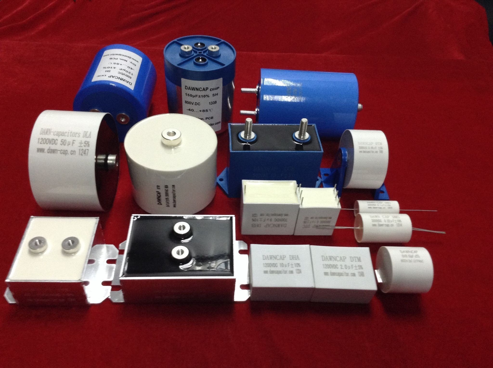
Capacitors are passive devices that serve unique functions in electronic circuits, including tuning, bypassing, coupling, and filtering. For instance, they are used in the tuning circuit of transistor radios, as well as in the coupling and bypass circuits of color TVs. As electronic information technology continues to advance rapidly, the update speed of digital electronic products has increased significantly. Capacitors play a crucial role in consumer electronic devices such as flat-panel TVs (LCD and PDP), notebook computers, digital cameras, and other similar products. Therefore, ensuring the capacitances and testing the quality of capacitors becomes extremely important. In this article, we will discuss in detail how to test and check a capacitor.
1 Test a Capacitor Using Multimeter
1.1 Digital Multimeter Use
1.1.1 Using Capacitance Gear
Some digital multimeters have the capability to measure capacitance, with five different ranges: 2000p, 20n, 200n, 2μ, and 20μ. To measure capacitance, follow these steps:
1. Insert the two pins of the discharged capacitor into the Cx jack on the meter board.
2. Select the appropriate range on the digital multimeter.
3. Read the displayed data.
🔺 The 2000p range is suitable for measuring capacitances less than 2000pF.
🔺 The 20n range is suitable for measuring capacitances between 2000pF and 20nF.
🔺 The 200n range is suitable for measuring capacitances between 20nF and 200nF.
🔺 The 2μ range is suitable for measuring capacitances between 200nF and 2μF.
🔺 The 20μ range is suitable for measuring capacitances between 2μF and 20μF.
It has been observed through experiments that some digital multimeters have large errors when measuring small capacitors below 50pF. Additionally, there is almost no reference value for measuring capacitors below 20pF. In such cases, the series method can be used to measure small-value capacitors. For example, to measure a capacitor of about 220pF:
1. Measure the actual capacity C1 of the capacitor with a digital multimeter.
2. Connect the small capacitor in parallel and measure the total capacity C2.
3. The difference between the two values (C1-C2) represents the capacity of the small capacitor. This method is highly accurate for measuring small capacitance in the range of 1-20pF.
1.1.2 Using Resistance Gear
In practice, a digital multimeter can be used to observe the charging process of a capacitor. The charging voltage is reflected as a discrete digital quantity, with n independent and successively increasing readings visible every second, assuming the measurement rate of the digital multimeter is n times/second. By analyzing these display values, the quality of the capacitor can be determined and the size of the capacitance can be estimated. This method is suitable for measuring large-capacity capacitors ranging from 0.1μF to several thousand microfarads.
1.1.3 Using Voltage Gear
Using a digital multimeter to detect capacitors with DC voltage is an indirect method. This method is capable of measuring small-capacity capacitors from 220pF to 1μF and accurately determining the size of the capacitor's leakage current.
1.1.4 Using the Buzzer
The buzzer function of a digital multimeter can be used to quickly check the quality of electrolytic capacitors. Follow these steps:
1. Set the digital multimeter to the buzzer position.
2. Use the test leads to contact the two pins of the capacitor (Cx) being tested.
3. A short buzzer sound should be heard initially, followed by the sound stopping and the overflow symbol "1" being displayed simultaneously.
4. Reverse the test leads for another measurement. The buzzer should sound again, and the overflow symbol "1" should be displayed.
5. This situation indicates that the measured electrolytic capacitor is basically normal.
6. To further determine the capacitor's quality, switch the digital multimeter to 20MΩ or 200MΩ to measure the leakage resistance of the capacitor.
1.2 Capacitor Measurements Matter
When measuring capacitors, it is important to follow certain guidelines to ensure accurate readings and prevent any issues. Here are some key points to keep in mind:
1. Before starting the measurement, make sure to short-circuit and discharge the two pins of the capacitor. This is important to avoid any interference during the reading process.
2. Avoid touching the capacitor electrode with both hands while conducting the measurement. This helps prevent any disruptions or jumps in the meter readings.
3. During the measurement process, the voltage value (Vin(t)) will change exponentially, with a rapid initial drop followed by a slower decline over time. When testing capacitors with a capacity of less than several thousand picofarads and using a low measurement rate, the initial display value on the meter may be lower than the battery voltage.
4. For capacitors with a capacitance value greater than 1μF, you can use the resistance gear to shorten the test time. On the other hand, when testing capacitors with a capacity of less than 200pF, it may be challenging to observe the charging process due to the minimal change in readings.
Remember to always cut off the power and discharge the capacitor before measuring. To discharge the capacitor, you can use a metal object like a screwdriver with an insulated handle. Hold the exposed part of the metal and touch the two pins of the capacitor. Once discharged, you can proceed with measuring the capacitance using a digital multimeter.
To measure the capacitance, locate the capacitor block and insert the two pins into the appropriate socket for capacitance measurement. Wait for the reading on the meter screen to stabilize. The displayed value represents the capacitance of the capacitor. If there is leakage, you can use an analog multimeter. Connect the two test leads of the multimeter to the capacitor, and observe the movement of the pointer. The pointer should deflect clockwise initially and then return counterclockwise to infinity as the capacitor is fully charged. The larger the angle of deflection, the greater the capacitance. A constant-speed deflection indicates no leakage.
If the needle slows down suddenly or does not return at a certain position on the dial, it indicates leakage in the capacitor during a specific period. If the display shows infinity at the end, it suggests no leakage, but this is only a rough judgment. For accurate measurements, a capacitance meter or observation of characteristics on a capacitance leakage tester or oscilloscope is required, which may not be accessible to ordinary individuals. Additionally, be cautious when selecting ceramic capacitors as their withstand voltage may not always be marked on the body.
1.3 Testing Non-polar Capacitors
To test non-polar capacitors, adjust the multimeter to the "diode" gear and measure the on-off state. If the multimeter displays "1," it indicates normal functioning. If it displays "0" or any other numbers, it means the capacitor is damaged.
1.4 Testing Polar Capacitors
Polar capacitors, such as electrolytic capacitors, have specific indications of damage. Look for signs like bulging, deformation, or leakage in the capacitor shell. To measure the quality of a polar capacitor using a digital multimeter:
1. Set the multimeter to the appropriate block based on the rated capacitance marked on the capacitor.
2. Insert the capacitor into the corresponding hole on the multimeter to measure its capacity.
If the measured capacitance falls within the rated value range, it indicates that the capacitor is intact. Otherwise, it is likely damaged.
1.5 Testing Chip Capacitors
To test chip capacitors, follow these steps:
1. Adjust the multimeter to the appropriate ohm gear. The gear selection principle is as follows: use a 20K gear for a 1μF capacitor, a 2K gear for a 1~100μF capacitor, and a 200 gear for capacitors larger than 100μF.
2. Determine the polarity of the capacitor. Start by adjusting the multimeter to 100 or 1K ohms. Assuming one pole is positive, connect the black test lead to it and the red test lead to the other pole. Note the resistance value and then discharge the capacitor. Change the test leads and measure the resistance again. The black test lead with a higher resistance value should be connected to the positive electrode of the capacitor.
3. Connect the red probe of the multimeter to the positive electrode of the capacitor and the black probe to the negative electrode. If the display gradually increases from 0 and shows the overflow symbol 1 at the end, it indicates that the capacitor is normal. If the display remains at 0, the capacitor is short-circuited. If 1 is displayed, it suggests an open internal circuit in the capacitor.
1.6 Testing Solid Capacitors
✔️ Capacitors Greater Than 20μF
When using a regular digital multimeter, the maximum measurement value for capacitors is 20μF, which may not be sufficient for testing capacitors larger than this value. To measure capacitors greater than 20μF or up to several thousand microfarads, you can use the following simple method without making any changes to the original circuit of the multimeter.
The measurement principle of this method is based on the formula for capacitors in series, C = C1C2/(C1+C2). Since two capacitors of different capacities are connected in series, the total capacity after the connection is smaller than the smaller capacitor. Therefore, if the capacitance of the capacitor being tested exceeds 20μF, you only need to connect it in series with a capacitor smaller than 20μF, and then you can directly measure it on the digital multimeter. Using the above formula, you can easily derive C1=C2C/(C2-C), and with this formula, you can calculate the capacitance of the capacitor being tested.
✔️ Capacitors Less Than 10μF
For fixed capacitors with a capacitance less than 10pF, their capacity is too small to be accurately measured with a multimeter. However, you can use the multimeter to roughly check for leakage, internal short circuits, or voltage breakdown. Select the R×10k range on the multimeter and connect the two test leads to any two terminals of the capacitor. The resistance should be infinite. If the measured resistance value (the pointer swings to the right) is zero, it indicates that the capacitor is damaged due to leakage or internal breakdown.
✔️ Capacitors Between 10pF and 0.01μF
To test whether a capacitor in this range is charged, you can use the multimeter to determine its condition. Select the R×1k range on the multimeter. The β value of the two transistors should be greater than 100, and the penetration current should be small. You can use a composite tube composed of silicon transistors. Connect the red and black test leads of the multimeter to the emitter e and collector c of the composite tube, respectively. Due to the amplification effect of the composite transistor, the charging and discharging process of the tested capacitor is amplified, and the pointer of the multimeter has a larger swing amplitude, making it easier to observe. It is important to note that during the testing process, especially when measuring capacitors with small capacities, you need to repeatedly exchange the contact points A and B of the tested capacitor to clearly observe the swing of the meter pointer.
✔️ Capacitors with a Fixed Capacitance of 0.01μF
For fixed capacitors with a capacitance greater than 0.01μF, you can directly test whether they have a charging process, internal short circuits, or leakage by using the R×10k range on the multimeter. The magnitude of the pointer swing to the right can be used to estimate the size of the capacitor.
1.7 Testing Electrolytic Capacitors
1) Due to the larger capacity of electrolytic capacitors compared to regular fixed capacitors, different ranges should be selected for measurement. As a general guideline, the R×1k range can be used to measure capacitors between 1μF and 47μF, and the R×100 range can be used for capacitors larger than 47μF.
2) Connect the red test lead of the multimeter to the negative terminal and the black test lead to the positive terminal of the electrolytic capacitor. Upon contact, the pointer of the multimeter will swing to a larger angle towards the right (for the same potential barrier, the larger the capacitance, the larger the swing), and then gradually rotate to the left until it stops at a certain position. The resistance value at this point is the forward leakage resistance of the electrolytic capacitor, which is slightly larger than the reverse leakage resistance. Practical experience shows that the leakage resistance of electrolytic capacitors should generally be greater than several hundred kilohms for normal operation. During testing, if there is no charging phenomenon in both forward and reverse directions, i.e., the hand does not move, it indicates that the capacitance has disappeared or the internal circuit is disconnected. If the measured resistance value is small or zero, it indicates a larger leakage or breakdown of the capacitor.
3) For electrolytic capacitors with unknown polarity, the above method of measuring leakage resistance can be used to differentiate. Randomly measure the leakage resistance and remember its value, then exchange the test leads to measure another resistance value. The larger resistance value between the two measurements indicates the positive connection, i.e., the black test lead is connected to the positive terminal and the red test lead is connected to the negative terminal. Use the multimeter to prevent current flow and charge the electrolytic capacitor. The amplitude of the pointer swing to the right can be used to estimate the capacitance of the electrolytic capacitor. When measuring electrolytic capacitors, if the measured values do not change significantly, swap the corresponding pins of the probes for multiple measurements.
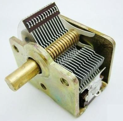
1.8 Testing Variable Capacitors
1) Gently and smoothly rotate the shaft. There should be no looseness when pushing the load shaft in all directions.
2) Rotate the shaft with one hand and lightly touch the outer edge of the film group with the other hand. There should be no looseness felt. Variable capacitors with poor contact between the rotating shaft and the movable plate cannot be used anymore.
3) Set the multimeter to the R×10k range. With one hand, connect the two test leads to the leads of the movable plate and fixed plate of the variable capacitor, and with the other hand, slowly rotate the shaft back and forth several times. The pointer of the multimeter should not move to infinity. During the rotation of the shaft, if the pointer sometimes points to zero, it indicates a short circuit between the movable plate and fixed plate. If at a certain angle, the multimeter reading is not infinite but a specific resistance value, it indicates leakage between the film plates of the variable capacitor.
1.9 Differentiating Capacitor Polarities
The black marked part on the capacitor is the negative pole. On the PCB board, there are two semicircles corresponding to the capacitor's position, and the pin corresponding to the colored semicircle is the negative pole. The length of the pins also helps differentiate the polarity: the longer pin is the anode, and the shorter pin is the cathode.
When we are unsure of the polarity of a capacitor, we can use a multimeter to determine it. The dielectric between the two poles of a capacitor is not an absolute insulator, and its resistance is not infinite but a finite value, generally greater than 1000 megohms. The resistance between the two poles of a capacitor is called insulation resistance or leakage resistance. Only when the positive pole of an electrolytic capacitor is connected to the positive terminal of the power supply (black test lead) and the negative pole is connected to the negative terminal (red test lead), the leakage current is small (leakage resistance is large). Otherwise, the leakage current increases (leakage resistance decreases).
In an unknown situation, you can assume a certain polarity for the "+ " pole. Use the R*100 or R*1K range of the multimeter, connect the test leads, and record the scale at which the test probe stops (the resistance value of the test probe is larger to the left).
2 Test a Capacitor Using Bridge
The accuracy of capacitance measurement using a multimeter is limited, as it can only provide a rough estimate of the capacitance value. However, for more precise measurements, professionals often use a bridge. By using a digital bridge to test a capacitor, you can connect the leads of the capacitor to accurately measure its capacitance. Additionally, the bridge can also indicate the loss of the capacitor, which is particularly useful in assessing the overall quality of the capacitor. By analyzing the loss, one can easily distinguish between different types of capacitors and their performance characteristics.
3 Test a Capacitor Using Professional Equipment
Capacitors require specific test equipment to evaluate their performance. Some of the commonly used tests include durability tests, destructive tests, loss angle tests, inter-electrode withstand voltage tests, self-healing tests, charge and discharge tests, pulse voltage tests, spontaneous combustion tests, and ripple current durability tests. However, these tests often require specialized and expensive equipment, making them challenging for most users to conduct.
If you need accurate and detailed test data, it is recommended to either entrust a third-party testing service or contact the manufacturer for relevant information. These external sources can provide the necessary expertise and equipment to perform the required tests and provide you with the desired data.
4 FAQ
1. How do you check if a capacitor is bad?
To check if a capacitor is bad, you can use a multimeter to read the voltage on the capacitor leads. The voltage should read near the rated voltage of the capacitor, typically around 9 volts. If the capacitor cannot retain this voltage or discharges rapidly to 0V, it is likely defective and should be replaced.
2. How do you tell if a capacitor is bad with a multimeter?
When using a multimeter to test a capacitor, if the capacitance value is within the measurement range of the multimeter, it will display the capacitor's value. However, if the capacitance value is higher than the measurement range or if the capacitor is faulty, the multimeter will display "OL" (open loop) or a similar indication.
3. What are the symptoms of a bad start capacitor?
Symptoms of a bad start capacitor in a motor include warm air flowing from the vents inside the home, the air conditioner taking longer than usual to kick on or turning off before it is programmed to, or a constant low hum emitting from the machine that is not typical.
4. Can a capacitor test good and still be bad?
Yes, it is possible for a capacitor to test within its specified tolerance range and still be bad. In such cases, the capacitance may be lower than its original value, but still within tolerance. Leakage is unlikely to be a problem. There are two ways to test a capacitor: using an ESR (equivalent series resistance) meter or an oscilloscope.
5. How long can a capacitor last?
Capacitors have a limited lifespan, and most are designed to last approximately 20 years. However, several factors can cause them to wear out more quickly.
6. How do you identify a capacitor?
Ceramic capacitors usually have a 3-digit code printed on their body to indicate their capacitance value in pico-farads (pF). The first two digits represent the capacitor's value, and the third digit indicates the number of zeros to be added.
7. Will a capacitor discharge on its own?
In theory, a capacitor will gradually lose its charge over time. When disconnected, a fully charged capacitor discharges to about 63% of its voltage after one time constant. After five time constants, the capacitor will discharge close to 0%.
8. How do I know if my AC capacitor is bad?
Common signs of a bad AC capacitor include the AC not blowing cold air, the AC taking longer than usual to start once turned on, a humming sound coming from the air conditioner, the AC shutting off on its own, or the AC not turning on at all.
9. What side of the capacitor is positive?
To determine the positive and negative sides of a capacitor, look for a large stripe or a minus sign (or both) on one side of the capacitor. The lead closest to this stripe or minus sign is the negative lead, while the other lead (which is unlabeled) is the positive lead.
10. Can I use a multimeter to discharge a capacitor?
A multimeter is not typically used to directly discharge the stored energy of a capacitor. Instead, it is used to measure the voltage and power of the capacitor to determine whether it is fully discharged or not. Other tools, such as a light bulb or a DIY discharge tool, are commonly used for the discharging process.
11. How fast can a capacitor discharge?
A fully charged capacitor discharges to about 63% of its voltage after one time constant. After five time constants, the capacitor will discharge close to 0% of its original voltage.
12. Can a bad capacitor ruin a compressor?
Using the wrong capacitor rating or a poor-quality capacitor can negatively affect the operation of the motor, the compressor, or even the entire HVAC system. This can lead to a reduction in the motor's overall speed, depending on the motor load.
13. Can I replace a start capacitor with a run capacitor?
Start capacitors have a large capacitance value necessary for motor starting for a short period of time. They cannot be used as run capacitors because they are not designed to handle continuous current.
14. How do you check a capacitor without a multimeter?
To check a capacitor without a multimeter, you can connect its terminals to a single-phase power supply and switch it on for a few seconds. Then, short the two terminals, and if you observe a spark, it indicates that the capacitor is in good condition.
15. What if a capacitor reads high?
If a capacitor reads a higher value than its nominal value, it may indicate a faulty capacitor. This could be due to an open circuit or other internal issues.
16. How many ohms should a capacitor have?
To measure the resistance of a capacitor, ensure that it is fully discharged and set the multimeter to the ohmic range (at least 1000 Ohms = 1kΩ). Then, connect the multimeter probes to the capacitor terminals, with the negative probe on the negative terminal and the positive probe on the positive terminal.
17. What if a capacitor reads low?
If a capacitor reads a lower value than its nominal value, it may indicate a faulty capacitor. Non-polar capacitors with values lower than 1μF should not change significantly with age. Capacitors used in frequency-sensitive circuits, such as filters or time delays, should have tighter tolerances.
18. What happens when a capacitor goes bad?
A faulty capacitor can prevent the exterior unit of an HVAC system from functioning properly, which hinders the overall cooling process. It can also result in improper voltage delivery to the exterior unit components, causing the system to work harder and potentially damaging other components.
19. How can you tell if a capacitor is bad?
Symptoms of defective capacitors may include excessive noise in audio or video, such as 60Hz audio hum or rolling bars in video, scratchy, distorted, or missing audio, low contrast, blurry, or distorted LCD displays, and intermittent or outright failure.
20. What does a damaged capacitor look like?
A damaged capacitor can be visibly broken, with signs such as leaking brownish fluid, corrosion, or severed leads. However, sometimes the signs are more subtle. The top of a blown capacitor may be slightly bent outwards in a convex shape, rather than flat or slightly indented like a working capacitor.


Company
About UsContact UsTerms & ConditionsPrivacy StatementPayment,Shipping & InvoiceRefund & Return PolicyWarranty PolicyFrequently asked questionHolidays for Chinese Mid-Autumn Festival and National Day in 2023 Copyright © 2022-2024 Power by Chipdatas Trading Limited. All Rights Reserved.